Cleaning blade packaging material
A technology for cleaning scrapers and packaging parts, which is applied in the direction of special packaging objects, packaging, and packaged foods. Excellent versatility
- Summary
- Abstract
- Description
- Claims
- Application Information
AI Technical Summary
Problems solved by technology
Method used
Image
Examples
Embodiment approach 1
[0034] [1. Package of cleaning scraper]
[0035] First, the package (hereinafter referred to as "package") of the cleaning blade according to the first embodiment (hereinafter referred to as "embodiment 1") of the present invention will be described. In addition, the details will be described later, but in Embodiment 1, the application Figure 8 (a), (b) shows the cleaning blade 100.
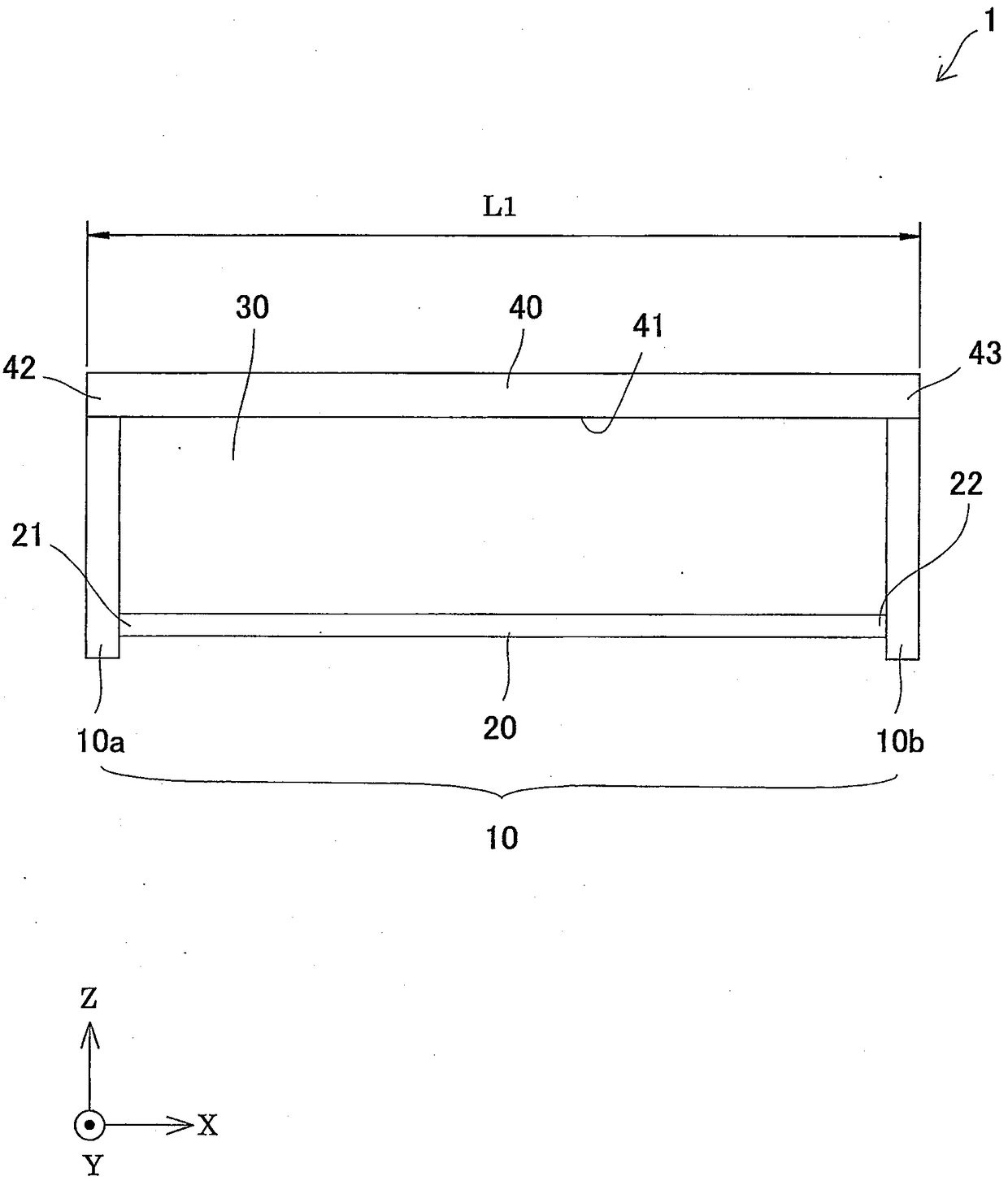
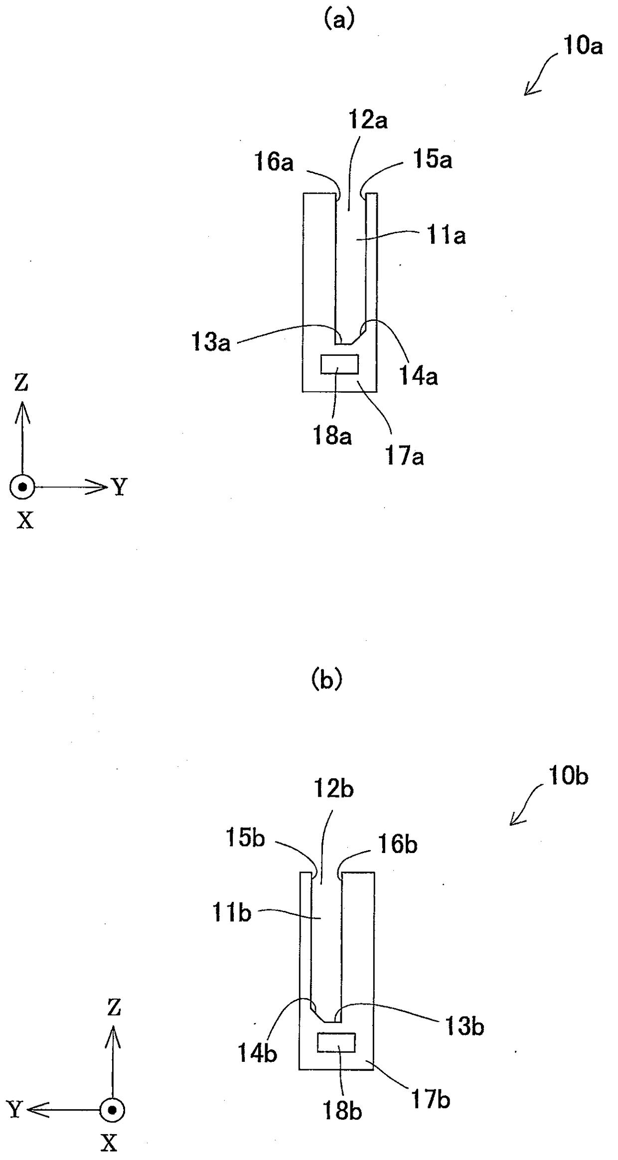
[0036] Such as Figure 1~Figure 3 and Figure 4 As shown in (a) and (b), the package 1 is a thin frame made of hard resin, and has a set of supporting part main bodies 10 for respectively supporting both ends of the cleaning blade 100 in the longitudinal direction, and a set of connecting parts. The connection part 20 of the support part main body 10, the storage part 30 which is the space between a set of support part main bodies 10, and the cover body 40 which closes the opening of the support part main body 10 of a set.
[0037]A set of support part main bodies 10 is comprised from the on...
Embodiment approach 2
[0064] A package of a second embodiment (hereinafter referred to as "embodiment 2") of the present invention will be described. Such as Figure 9 and Figure 10 As shown in (a) and (b), the package 2 is a modified example of the package 1 of the first embodiment, except that the package 2 has a structure capable of restricting the movement of the housed cleaning blade 100 in the longitudinal direction (X direction). The structure of the package 1 is the same as that of the package 1 except for a set of supporting part main bodies 70 . Therefore, in Embodiment 2, only the difference between the package 2 and the package 1 will be described, and other descriptions will be omitted.
[0065] One set of support body bodies 70 is composed of one first support body body 71a and the other second support body body 71b, and the first support body body 71a is reversed in mirror image to form the second support body body 71b. A part of the side wall 72a of the first support body 71a pr...
Embodiment approach 3
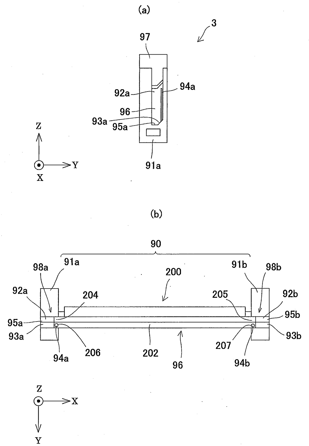
[0072] A package of a third embodiment (hereinafter referred to as "embodiment 3") of the present invention will be described. In addition, in Embodiment 3, as Figure 11 As shown in (b), the cleaning blade 200 having the same structure as the cleaning blade 100 used in Embodiment 1 is used except that the positions where the holes 206 and 207 are formed are different. Such as Figure 11 As shown in (a) and (b), the package 3 is a modified example of the package 1 in Embodiment 1, except that a set of support parts having a structure capable of restricting the movement of the housed cleaning blade 200 in the longitudinal direction is used. Except for the main body 90, the structure is the same as that of the package 1. Therefore, in Embodiment 3, only the difference between the package 3 and the package 1 will be described, and other descriptions will be omitted.
[0073] One set of support body bodies 90 is composed of one first support body body 91a and the other second s...
PUM
 Abstract
Description
Claims
Application Information
 - R&D
- Intellectual Property
- Life Sciences
- Materials
- Tech Scout
- Unparalleled Data Quality
- Higher Quality Content
- 60% Fewer Hallucinations
Browse by: Latest US Patents, China's latest patents, Technical Efficacy Thesaurus, Application Domain, Technology Topic, Popular Technical Reports.
© 2025 PatSnap. All rights reserved.Legal|Privacy policy|Modern Slavery Act Transparency Statement|Sitemap|About US| Contact US: help@patsnap.com


