Double-layer ring truss antenna mechanism driven by elastic hinge

A ring truss and elastic hinge technology, applied in the direction of folding antennas, etc., can solve the problems of inability to meet the rigidity requirements, low deployment reliability, complex drive mechanism, etc., and achieve enhanced overall rigidity and repeated deployment accuracy, kinematic mechanism and control system Simple, good node integrity

Active Publication Date: 2017-01-18
HARBIN INST OF TECH
View PDF3 Cites 0 Cited by
  • Summary
  • Abstract
  • Description
  • Claims
  • Application Information

AI Technical Summary

Problems solved by technology

[0004] The present invention aims to solve the problem that the stiffness of the existing single-ring ring truss mechanism decreases with the increase of the antenna caliber, which cannot meet the rigidity requirements for use, and the existing ring truss antenna has a complex drive mechanism, heavy mechanism weight, and low deployment reliability. problem, and then provide an elastic hinge-driven double-layer ring truss antenna mechanism

Method used


Image

  • Double-layer ring truss antenna mechanism driven by elastic hinge
  • Double-layer ring truss antenna mechanism driven by elastic hinge
  • Double-layer ring truss antenna mechanism driven by elastic hinge

Examples


specific Embodiment approach 1

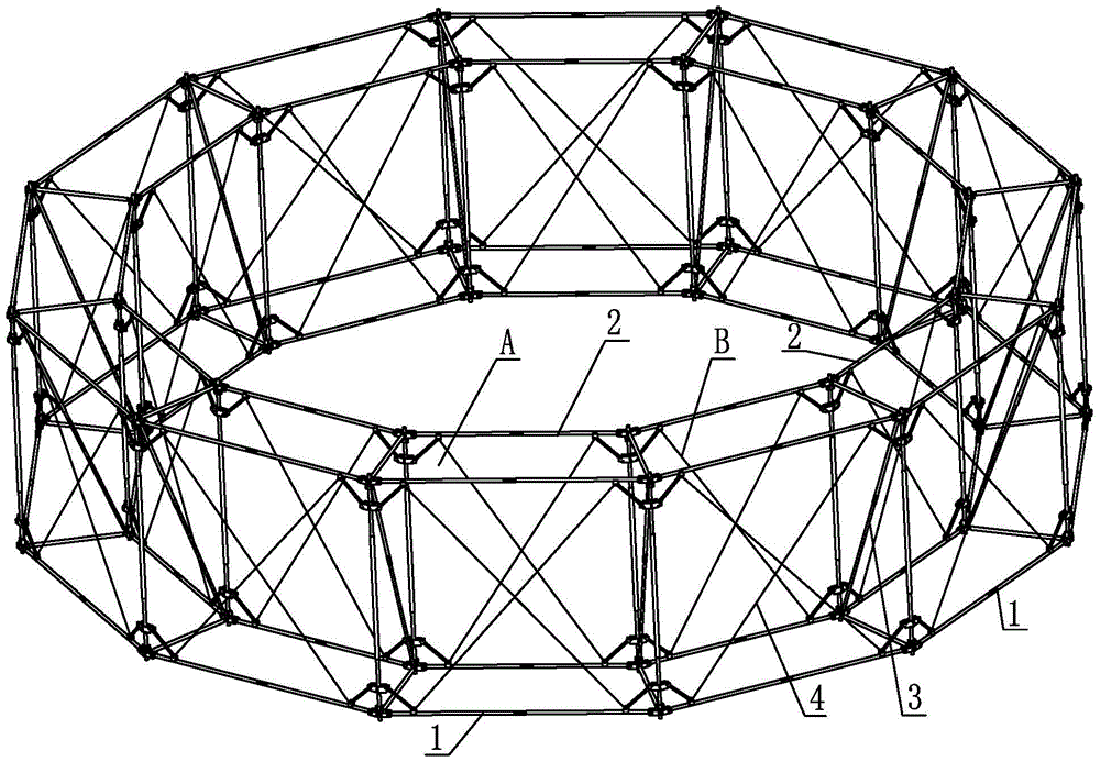
[0017] Specific implementation mode one: combine Figure 1-Figure 10 Explain that the elastic hinge-driven double-layer ring truss antenna mechanism of this embodiment includes an inner ring ring truss assembly 2, an outer ring ring truss assembly 1, a plurality of inner and outer ring connecting truss assemblies 3 and a plurality of cable assemblies 4; The ring ring truss assembly 2 and the outer ring truss assembly 1 have the same structure, and both the inner ring truss assembly 2 and the outer ring truss assembly 1 include a plurality of elastic hinge-driven expandable units A and a plurality of elastic hinge-driven transition folds. Expansion component B, the foldable unit A driven by two adjacent elastic hinges in the inner ring truss component 2 is connected through the transitional expansion component B driven by the elastic hinge, and the two adjacent elastic hinges in the outer ring truss component 1 are driven The foldable unit A is connected by a transitional folda...

specific Embodiment approach 2

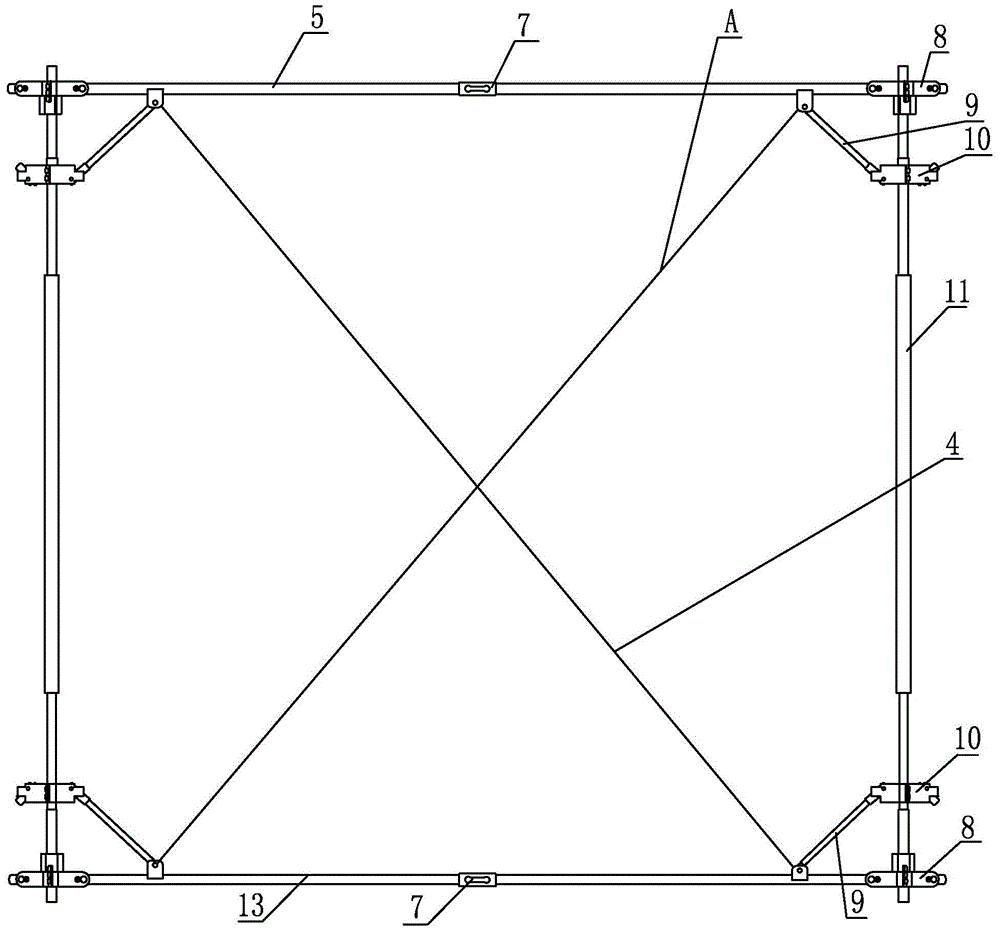
[0019] Specific implementation mode two: combination figure 1 , image 3 and Figure 5 Explain that each elastic hinge-driven expandable unit in this embodiment includes two upper chords 5, two lower chords 13, two chords that drive elastic hinges 7, two support vertical bars 11, four Self-locking hinge 8, four cranks 9 and four slide blocks 10;

[0020] A self-locking hinge 8 is respectively connected to the upper end and the lower end of the two support vertical bars 11, and two upper chords 5 and two lower chords 13 are arranged between the two support vertical bars 11, and the two chords of the elastic hinge 7 are driven by the chords. Each end is affixed to one end of an upper chord 5, and the two ends of the chord expansion drive elastic hinge 7 are respectively affixed to one end of a lower chord 13, and the other ends of the two upper chords 5 are hinged to the corresponding self-locking hinge 8 , the other ends of the two lower chords 13 are hinged with the corresp...

specific Embodiment approach 3

[0023] Specific implementation mode three: combination figure 1 , image 3 and Figure 6 Note that each of the inner and outer ring connection truss assemblies 3 in this embodiment includes an upper cross bar 28, a lower cross bar 29, a diagonal upper chord 15, a diagonal lower chord 17, and a chord expansion driving elastic hinge 7;

[0024] Between the diagonal upper chord 15 and the diagonal lower chord 17 is arranged a chord fixedly connected with the two to expand and drive the elastic hinge 7, the upper cross bar 28, the lower cross bar 29, the diagonal upper chord 15, and the diagonal lower chord 17 The elastic hinges 7 driven by the chords are arranged in a Z shape, the upper diagonal chords 15 are hinged with the self-locking hinges 8 on the outer ring truss assembly 1, and the lower diagonal chords 17 are hinged with the self-locking hinges on the inner ring truss assembly 1 8 hinged, the upper cross bar 28 is hinged between the two self-locking hinges 8 on the upp...


PUM


Abstract

The invention discloses an elastic-hinge-driven double-layer annular truss antenna mechanism, relates to an unfoldable antenna mechanism and aims to solve the problems that an existing monocyclic annular truss mechanism is decreased in rigidity along with increase of the antenna aperture and thereby cannot achieve the use stiffness requirements, and an existing annular truss antenna is complex in driving mechanism, large in mechanism weight and quite low in unfolding reliability. The elastic-hinge-driven double-layer annular truss antenna mechanism comprises inner-ring annular truss components, outer-ring annular truss components, a plurality of inner-and-outer-ring connection truss components and a plurality of inhaul cable components, each of the inner-ring annular truss components and the outer-ring annular truss components comprises a plurality of elastic-hinge-driven foldable and unfoldable units and a plurality of elastic-hinge-driven transition foldable and unfoldable components, each two adjacent elastic-hinge-driven foldable and unfoldable units are connected through the corresponding elastic-hinge-driven transition foldable and unfoldable component, and four corresponding vertex angles between each inner-ring annular truss component and the corresponding outer-ring annular truss component are supported and are connected rotatably by one inner-and-outer-ring connection truss component. The elastic-hinge-driven double-layer annular truss antenna mechanism is used for satellites, space stations and space probes.

Description

technical field [0001] The invention relates to a deployable antenna mechanism, in particular to a double-layer ring-shaped truss-type deployable antenna, which belongs to the technical field of aerospace equipment and equipment. Background technique [0002] With the rapid development of space communication, earth observation, deep space exploration, and manned spaceflight, the demand for large-scale, lightweight, and high-geometric stability aerospace space agencies has become very urgent, but limited by the volume of the rocket fairing Due to the limitation of space travel, it is necessary to design a space-expandable mechanism with a large expansion ratio, which is in a folded state during the transportation and launch stages, and unfolds into a working state after the spacecraft enters orbit. The design and related research of the space folding mechanism is one of the key fundamental issues in the development of the future aerospace industry. With the gradual developme...

Claims


Application Information

Patent Timeline
Patent Type & Authority Patents(China)
IPC IPC(8): H01Q1/08
Inventor 郭宏伟邓宗全史创刘荣强
Owner HARBIN INST OF TECH
Why Eureka
Try Eureka