Torsion spring driven shear hinge ring rib type deployable antenna mechanism

A torsion spring and antenna technology, which is applied in directions such as antennas, antenna supports/installation devices suitable for movable objects, etc., can solve the problems of complex deployable antenna mechanisms, poor rigidity and strength, and low reliability, and saves transmission. The effect of space, weight reduction, and large folding ratio

Pending Publication Date: 2022-07-29
YANSHAN UNIV
View PDF0 Cites 0 Cited by
  • Summary
  • Abstract
  • Description
  • Claims
  • Application Information

AI Technical Summary

Problems solved by technology

[0004] Aiming at the problems existing in the prior art, the present invention provides a torsion spring-driven scissor-hinge rib-type deployable antenna mechanism, which drives the movement of the folding rod through the torsion spring, and the scissor rods and folding rods are jointly driven to ensure the synchronization of the mechanism deployment. and the stability of the overall structure during the movement, by changing the number of radial expandable units and circumferential expandable units and the lengths of the scissor rods and folding rods that constitute the units, an expandable antenna mechanism with any caliber size is formed, It solves the problems of complex structure, low reliability and poor rigidity of existing deployable antennas, and is better applied to communication satellites, space stations and space probes

Method used


Image

  • Torsion spring driven shear hinge ring rib type deployable antenna mechanism
  • Torsion spring driven shear hinge ring rib type deployable antenna mechanism
  • Torsion spring driven shear hinge ring rib type deployable antenna mechanism

Examples


Embodiment

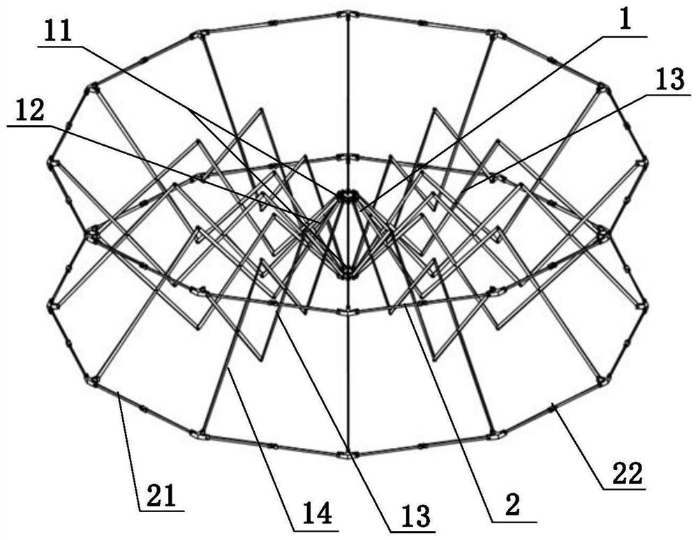
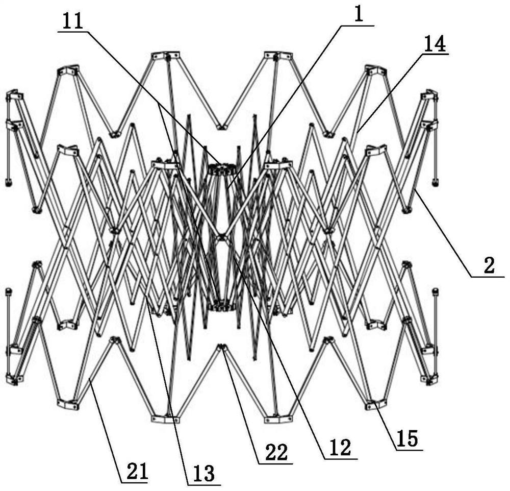
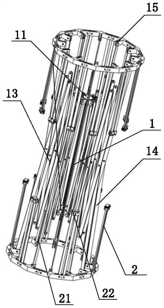
[0034] In this embodiment, the torsion spring-driven scissor hinge ring rib-type deployable antenna mechanism includes N radially deployable units 1 and N circumferentially deployable units 2, where N is an integer greater than or equal to 3, and the radially deployable unit The exhibition units 1 are connected to each other by sharing two inner faceplates 11 and N circumferentially deployable units 2, and the multiple circumferentially deployable units 2 are connected end to end through the shared two outer faceplates 15 to form a circumferential annular truss assembly. , the circumferential annular truss components are all multi-faceted annular truss structures after being unfolded and folded.

[0035] The operation process of this embodiment is implemented as follows:

[0036] The torsion spring-driven scissor-hinged ring-rib-type deployable antenna mechanism of the present invention can adjust the size and quantity of the radially deployable unit 1 and the circumferentiall...


PUM


Abstract

The invention provides a torsional spring driven shear-hinge ring rib type deployable antenna mechanism, which comprises radial deployable units and circumferential deployable units, each radial deployable unit comprises an inner faceplate, a first shear-fork rod, a second shear-fork rod, a third shear-fork rod and an outer faceplate, and the radial deployable units are arranged on the outer side of the inner faceplate in a circumferential array manner; the radial deployable units are connected with the circumferential deployable units through the outer disc chucks, the circumferential deployable units are sequentially connected end to end through the outer disc chucks, each circumferential deployable unit comprises a folding rod and a torsional spring driving assembly, and the folding rods are connected through the torsional spring driving assemblies. By adjusting the number of the radial deployable units and the circumferential deployable units and the lengths of the scissor rods and the folding rods forming the units, the deployable antenna mechanism with any caliber is formed, and the deployable antenna mechanism has the advantages of being good in manufacturability, high in rigidity, large in folding ratio and the like; the problems that an existing deployable antenna is complex in mechanism, low in reliability, poor in rigidity and strength and the like are solved, and the antenna can be better applied to communication satellites, space stations and space detectors.

Description

technical field [0001] The invention relates to the technical field of antenna mechanisms, in particular to a torsion spring driven scissor hinge ring rib type deployable antenna mechanism. Background technique [0002] With the needs of communication, space science, earth observation and national defense construction, the needs of various countries for large space antennas are becoming more and more urgent. When the size of the antenna exceeds the range that the launch vehicle fairing (or the space shuttle) can accommodate, the structure of the deployable antenna must be adopted. During the launch phase, these large antennas have to be folded up, and after the spacecraft has entered a predetermined orbit, it is then deployed into a working state by an actuator. Space deployable mechanisms are widely used in communication satellite platforms, space stations, space telescopes, spacecraft and other spacecraft due to the advantages of light weight, small footprint, and easy st...

Claims


Application Information

Patent Timeline
IPC IPC(8): H01Q1/12H01Q1/20H01Q1/27H01Q1/28
CPCH01Q1/1235H01Q1/20H01Q1/288H01Q1/27
Inventor 韩博李潇涵李祥鲲高超姚宇先苑展图
Owner YANSHAN UNIV
Why Eureka
Try Eureka