A series hybrid permanent magnet variable flux motor

A hybrid permanent magnet and variable magnetic flux technology, applied in the direction of magnetic circuits, electromechanical devices, electrical components, etc., can solve the problems of limited magnetic field weakening capability, large current, large direct-axis reluctance and quadrature-axis reluctance, etc.

Active Publication Date: 2021-05-11
HUAZHONG UNIV OF SCI & TECH
View PDF8 Cites 2 Cited by
  • Summary
  • Abstract
  • Description
  • Claims
  • Application Information

AI Technical Summary

Problems solved by technology

However, this method still has shortcomings: first, due to the large reluctance of the permanent magnet, the direct axis inductance is usually small, so a large field-weakening current is required, and the field-weakening capability is limited, and the motor speed regulation range is narrow; second , the weak magnetic current will introduce additional copper loss, and the copper loss is proportional to the square of the current. As the speed increases, the amplitude of the weak magnetic current increases, and the loss from the weak magnetic tape will increase significantly, reducing the efficiency of the motor. ; Third, limited by the capacity of the inverter, the increase of the field-weakening current will inevitably reduce the torque current component, thereby reducing the torque output capability of the motor in the high-speed range
However, in this structure, the high-coercivity permanent magnet and the low-coercivity permanent magnet are directly placed together, and the magnetic flux passing through the high-coercivity permanent magnet all passes through the low-coercivity permanent magnet. The permanent magnet has a very strong magnetization effect on the low-coercivity permanent magnet, which will lead to a large current required for demagnetization of the low-coercivity permanent magnet and a narrow magnetic adjustment range
In order to increase the range of magnetic adjustment, we can only increase the thickness ratio of the low-coercivity permanent magnet to the high-coercivity permanent magnet, but it will also further increase the required charge and demagnetization current.
Moreover, the direct-axis reluctance and quadrature-axis reluctance of the rotor with this structure are very large, the direct-axis inductance and the quadrature-axis inductance are small and the difference is not large, that is, the salient pole ratio is not large, and the reluctance torque is small. The moment density is still not high enough

Method used


Image

  • A series hybrid permanent magnet variable flux motor
  • A series hybrid permanent magnet variable flux motor
  • A series hybrid permanent magnet variable flux motor

Examples


Embodiment Construction

[0037] In order to make the object, technical solution and advantages of the present invention clearer, the present invention will be further described in detail below in conjunction with the accompanying drawings and embodiments. It should be understood that the specific embodiments described here are only used to explain the present invention, not to limit the present invention. In addition, the technical features involved in the various embodiments of the present invention described below can be combined with each other as long as they do not constitute a conflict with each other.

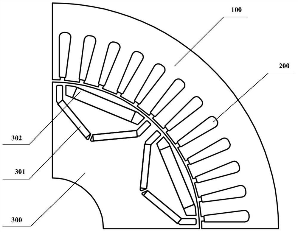
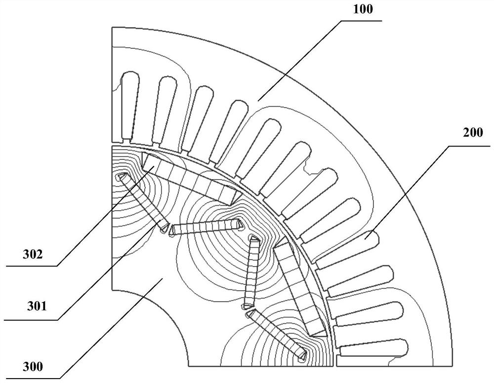
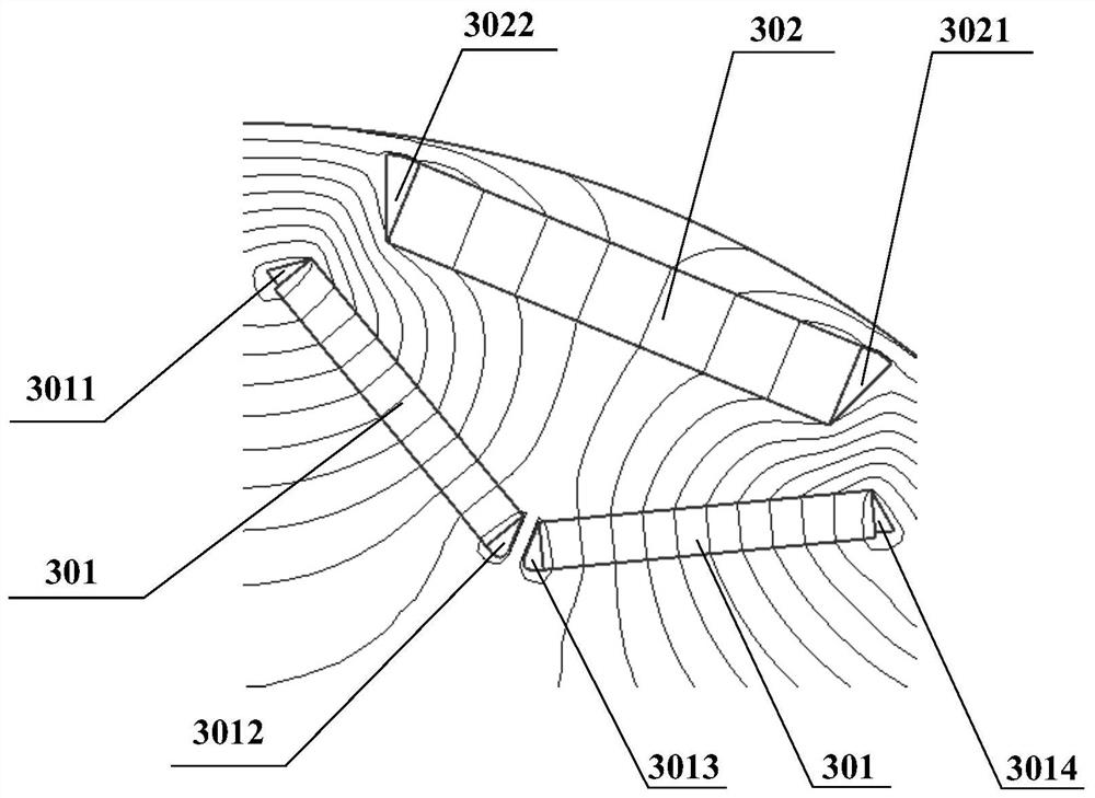
[0038]In the series hybrid permanent magnet variable flux motor, if the high-coercivity permanent magnet and the low-coercivity permanent magnet are directly placed together, the magnetic flux passing through the high-coercivity permanent magnet will all pass through the low-coercivity permanent magnet , at this time, the high coercive force permanent magnet has a very strong magnetizing effect ...


PUM


Abstract

The invention discloses a serial hybrid permanent magnet variable flux motor, which comprises a stator (100), an armature winding (200) wound on the stator (100), and a rotor core (300). Each pole of (300) is provided with three permanent magnets that are not in direct contact and placed separately, wherein the second permanent magnet (302) is placed on the outside in a "one" shape, and the two first permanent magnets (301) are in a "V" shape. ” shape is placed on the inner side, the second permanent magnet (302) is a high coercive force permanent magnet or a low coercive force permanent magnet, and the first permanent magnet (301) is a high coercive force permanent magnet or a low coercive force permanent magnet force permanent magnet. In the motor of the present invention, the low coercive force permanent magnet and the high coercive force permanent magnet adopt special placement positions and methods, so that the motor is a magnetic circuit series structure, and the high coercive force permanent magnet acts on the low coercive force permanent magnet. The magnetization effect improves the working point and magnetization degree of the low-coercivity permanent magnet, improves the torque output capability, and reduces the magnetizing current of the motor.

Description

technical field [0001] The invention belongs to the technical field of hybrid permanent magnet motors, and more specifically relates to a serial hybrid permanent magnet variable flux motor. Background technique [0002] In recent years, permanent magnet synchronous motors have been widely used in transportation, industry, and national defense due to their high efficiency, high power density, and good mechanical properties. However, with the expansion of the application field, the traditional permanent magnet synchronous motor has also exposed some shortcomings. The magnetization state of the permanent magnet in the traditional permanent magnet motor is difficult to change, and the no-load back EMF will increase with the increase of the speed. Since the terminal voltage of the motor cannot exceed the voltage limit value output by the inverter, continuous field weakening control is required in the high-speed range, that is, the permanent magnet magnetomotive force is offset b...

Claims


Application Information

Patent Timeline
Patent Type & Authority Patents(China)
IPC IPC(8): H02K1/27
CPCH02K1/2766
Inventor 李健徐海葛梦
Owner HUAZHONG UNIV OF SCI & TECH
Why Eureka
Try Eureka