Motor rotors and permanent magnet motors

A technology for motor rotors and permanent magnet motors, applied in magnetic circuits, electromechanical devices, electrical components, etc., can solve the problems of reduced motor efficiency, large charging and demagnetizing currents, and difficult adjustment of magnetic fields, so as to improve the equivalent coercive force and improve Effect of demagnetizing current and improving motor efficiency

Active Publication Date: 2020-09-01
GREE ELECTRIC APPLIANCES INC +1
View PDF8 Cites 0 Cited by
  • Summary
  • Abstract
  • Description
  • Claims
  • Application Information

AI Technical Summary

Problems solved by technology

[0002] Traditional permanent magnet motors rely on permanent magnets to provide magnetic flux, but permanent magnets provide a fixed magnetic field, and the internal magnetic field of the motor is difficult to adjust, making it difficult for permanent magnet motors to take into account the efficiency of high frequency and low frequency
And when the power supply voltage is fixed, the maximum operating frequency of the motor is limited
[0003] At present, most of the shortcomings of the internal magnetic field of permanent magnet motors are difficult to adjust, which leads to the limitation of the maximum speed of the motor by the input DC bus voltage and other factors, and the difficulty of taking into account the efficiency of the low-speed and high-speed operating regions of the motor. Force magnetic steel is affected by high coercive force magnetic steel, the charging and demagnetizing current is large, which will increase the difficulty of charging and demagnetizing low coercive force magnetic steel, and reduce the efficiency of the motor

Method used


Image

  • Motor rotors and permanent magnet motors
  • Motor rotors and permanent magnet motors
  • Motor rotors and permanent magnet motors

Examples


Embodiment Construction

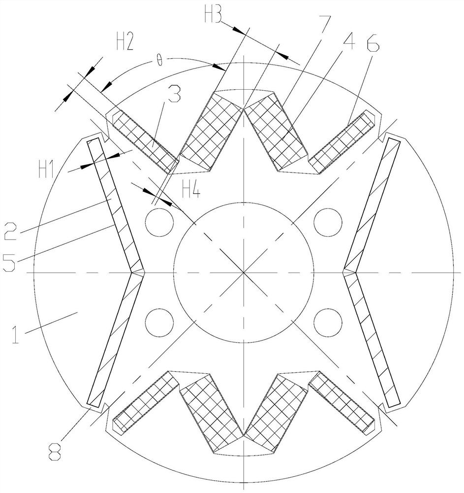
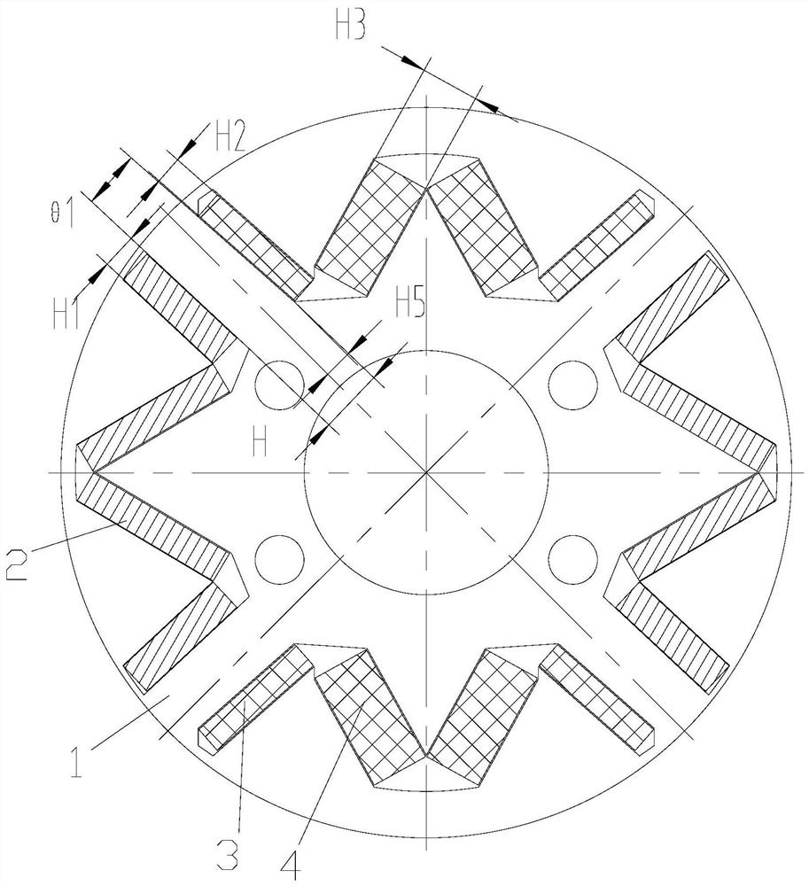
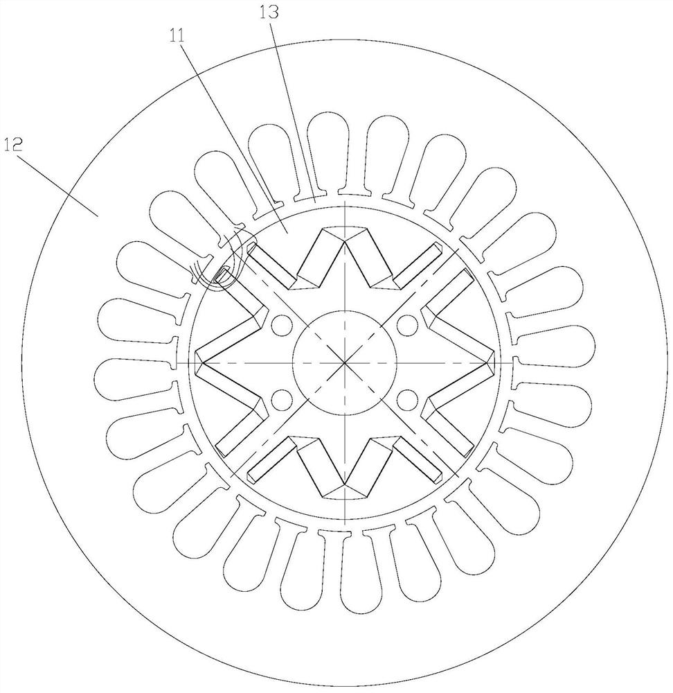
[0046] see in conjunction Figures 1 to 8 As shown, according to the embodiment of the present invention, the motor rotor includes a rotor core 1 and first permanent magnet poles and second permanent magnet poles arranged alternately along the circumferential direction of the rotor core 1, and the alignment of the permanent magnets on the first permanent magnet poles The coercive force is higher than the coercive force of the permanent magnet on the second permanent magnet pole.

[0047] The above-mentioned permanent magnet is, for example, magnet steel.

[0048] The permanent magnets on the first permanent magnet pole and the permanent magnets on the second permanent magnet pole adopt at least two types of magnetic steel grades with coercivity respectively, so that permanent magnet structures with different coercive forces are formed on the two permanent magnet poles. The permanent magnet structures with different coercivity are located at different magnetic poles, so the lo...


PUM


Abstract

The invention provides a motor rotor and a permanent magnet motor. The motor rotor comprises a rotor core (1), first permanent magnetic poles and second permanent magnetic poles, wherein the first permanent magnetic poles and the second permanent magnetic poles are alternately arranged in the circumferential direction of the rotor core (1); and the coercive force of permanent magnets on the firstpermanent magnetic poles is higher than the coercive force of permanent magnets on the second permanent magnetic poles. According to the motor rotor, the magnetizing current of the motor can be effectively decreased, the demagnetizing current of the motor can be increased, the stability of the magnetic loop during normal operation of the motor can be ensured, and the efficiency of the motor can beimproved.

Description

technical field [0001] The invention belongs to the technical field of motors, and in particular relates to a motor rotor and a permanent magnet motor. Background technique [0002] Traditional permanent magnet motors rely on permanent magnets to provide magnetic flux, but permanent magnets provide a fixed magnetic field, and the internal magnetic field of the motor is difficult to adjust, making it difficult for permanent magnet motors to take into account the efficiency at high and low frequencies. And in the case of a fixed power supply voltage, the maximum operating frequency of the motor is limited. [0003] At present, most of the shortcomings of the internal magnetic field of permanent magnet motors are difficult to adjust, which leads to the limitation of the maximum speed of the motor by the input DC bus voltage and other factors, and the difficulty of taking into account the efficiency of the low-speed and high-speed operating regions of the motor. Power magnetic ...

Claims


Application Information

Patent Timeline
Patent Type & Authority Patents(China)
IPC IPC(8): H02K1/27
CPCH02K1/2773H02K2213/03
Inventor 魏会军周博陈华杰孙文娇高明世
Owner GREE ELECTRIC APPLIANCES INC
Why Eureka
Try Eureka