
Neutron collimator structure with continuously adjustable divergence angle and its calibration method

A calibration method and divergence angle technology, applied in the direction of using aperture/collimator, instrument, radiation measurement, etc., can solve the problems of limited space of shielding body, inability to install collimator, inability to use demand adjustment, etc., to achieve optimization The effect of convenience and precision

Active Publication Date: 2020-06-23
CHINA INSTITUTE OF ATOMIC ENERGY
View PDF8 Cites 1 Cited by
  • Summary
  • Abstract
  • Description
  • Claims
  • Application Information

AI Technical Summary

Problems solved by technology

[0004] The neutron divergence angle of the neutron collimator currently used is determined at the time of manufacture and cannot be adjusted according to the use requirements; in addition, the neutron collimator is generally placed inside the shield and cannot be replaced at any time according to the needs. Collimator with divergence angle
Therefore, in order to complete different neutron experiments, the current general neutron spectrometer will pre-install several neutron collimators with commonly used divergence angles in the shielding body, but due to the limited space inside the shielding body, it is impossible to install the required collimators. collimator, still can not meet the requirements of all neutron experiments, and it takes a long time to replace the collimator, and it takes a lot of money to buy a variety of different types of collimators

Method used


Image

  • Neutron collimator structure with continuously adjustable divergence angle and its calibration method
  • Neutron collimator structure with continuously adjustable divergence angle and its calibration method
  • Neutron collimator structure with continuously adjustable divergence angle and its calibration method

Examples


Embodiment Construction

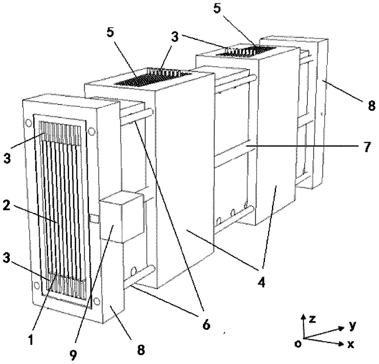
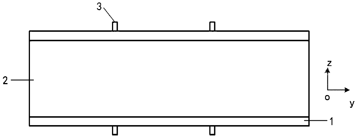
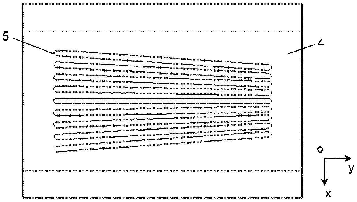
[0035] The disclosure provides a neutron collimator structure with continuously adjustable divergence angle and its calibration method. By setting a movable adjustment slider, an adjustment groove with a gradually changing spacing is set on the adjustment slider. The adjustment groove is parallel to the Several pieces of neutron absorbing layers are set correspondingly, and the adjusting column (fixed) on each piece of neutron absorbing layer is in the process of adjusting the slider moving (adjusting slider moving), the adjusting column corresponds to different positions of the adjusting groove, thereby changing The neutron absorbing layer spacing corresponding to the neutron incident direction can realize the continuous adjustment of the neutron divergence angle. In a neutron collimator structure, the adjustment of the divergence angle can be realized according to the actual needs, which can meet the requirements of various neutron experiments. .

[0036] In order to make th...


PUM


Abstract

The invention discloses a neutron collimator structure with continuously adjustable divergence angles and a calibration method of the structure. The neutron collimator structure comprises a pluralityof parallel neutron absorption layers, an adjusting slider and a driving structure. Adjusting columns are fixed to the upper portion and the lower portion of each neutron absorption layer, the adjusting slider with a hollow frame structure is arranged outside the neutron absorption layers, adjusting grooves are formed in the upper surface and the lower surface of the adjusting slider, the number of the adjusting grooves corresponds to that of the neutron absorption layers, the distances among the adjusting grooves are gradually changed along the parallel arrangement direction of the neutron absorption layers, the adjusting columns of the neutron absorption layers extend into the adjusting grooves, the driving structure drives the adjusting slider to move along the parallel arrangement direction of the neutron absorption layers, so that the positions of the adjusting columns in the adjusting grooves are adjusted, the distances among the neutron absorption layers are changed, and the neutron divergence angles are continuously adjusted. The divergence angles can be adjusted as required, experimental requirements of various neutrons are met, and neutron streaming time and expenditure are saved.

Description

technical field [0001] The disclosure belongs to neutron optical devices, and relates to a neutron collimator structure with continuously adjustable divergence angle and a calibration method thereof, in particular to a neutron collimator with continuously adjustable divergence angle based on changing the distance between neutron absorbing layers neutron collimator structure, and the calibration method of the divergence angle of the neutron collimator structure. Background technique [0002] The neutron scattering spectrometer uses a large number of neutrons of different energies produced by reactors, spallation sources, etc. It is an instrument for studying the stress, texture, microstructure and magnetic correlation properties of samples. [0003] Because the neutrons produced by the reactor or spallation source scatter toward the 4π direction, the divergence angle of the neutron beam drawn from the tunnel is very large, and the measurement of the momentum change requires ...

Claims


Application Information

Patent Timeline
Patent Type & Authority Patents(China)
IPC IPC(8): G21K1/02G01T7/00
CPCG01T7/005G21K1/02
Inventor 陈东风李玉庆孙凯刘蕴韬韩松柏焦学胜王洪立李眉娟贺林峰刘晓龙郝丽杰武梅梅魏国海韩文泽
Owner CHINA INSTITUTE OF ATOMIC ENERGY
Learn More