Sensor connecting assembly and track transportation system

A technology for connecting components and sensors, which is applied in locomotives, railway signals and safety, etc., and can solve problems such as deviation of the sensing range and failure of the sensor 3' to achieve the expected effect

Pending Publication Date: 2019-04-26
EUROCRANE
View PDF0 Cites 4 Cited by
  • Summary
  • Abstract
  • Description
  • Claims
  • Application Information

AI Technical Summary

Problems solved by technology

However, because there is a movement deviation along the extension direction of the vertical rail 6' when the running car 7' runs along the track 6', the center of the running car 7' deviates from the center line of the track 6', and the measuring end 32' produces a vertical line along with the running car 7'. The movement deviation of the extension direction of the track 6' causes the sensing range of the measuring end 32' to deviate from the position of the positioning end 31', and the sensor 3' cannot achieve the expected effect

Method used


Image

  • Sensor connecting assembly and track transportation system
  • Sensor connecting assembly and track transportation system
  • Sensor connecting assembly and track transportation system

Examples


Embodiment 1

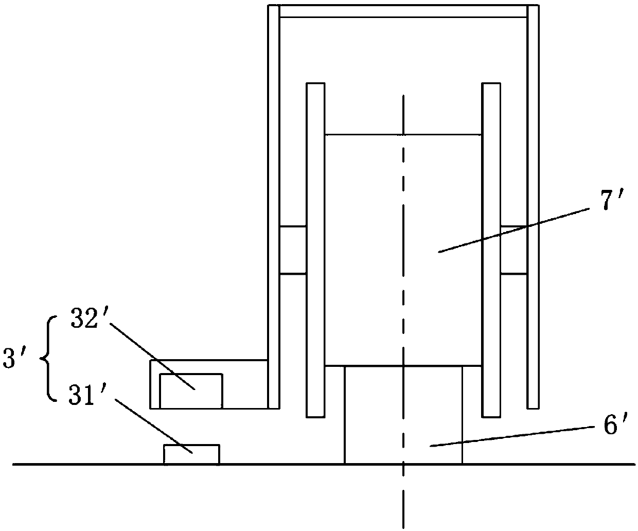
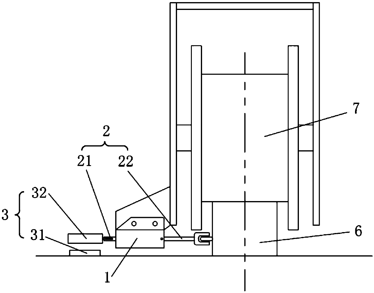
[0036] Such as figure 2 As shown, this embodiment provides a rail transportation system, including a rail 6 and a running vehicle 7 running along the rail 6 . In order to detect and control the running process of the running vehicle 7 along the track 6, a sensor 3 can be installed in the track transportation system. The sensor 3 may include a positioning end 31 and a measuring end 32. When the vehicle 7 runs to a preset position, the positioning end 31 is within the detection range of the measuring end 32, and the measuring end 32 can output a signal. The sensor 3 can be a magnetic sensor, the measuring end 32 can be a magnetic field detection end, and the positioning end 31 can be a magnetic block; certainly in other embodiments, the sensor 3 can also be a photoelectric sensor, the positioning end 31 can be a transmitter, and the measuring end 32 can be a magnetic block. It can be a receiver; and other sensors 3 capable of realizing the detection function can be adopted. T...

Embodiment 2

[0047] During the running of the trolley 7 along the track 6, the track 6 is prone to wear and tear, so that the surface of the track 6 has unevenness such as pits. When the guide wheel 221 abuts against the rail 6 , affected by the surface quality of the rail 6 , a movement deviation perpendicular to the extending direction of the rail 6 occurs. In order to solve this problem, this embodiment provides a rail transportation system and a sensor connection assembly. The rail transport system differs from Embodiment 1 in that, as Figure 5-6 As shown, the rail transportation system further includes a guide rail 5 , the extension direction of the guide rail 5 is parallel to the extension direction of the rail 6 . The guide wheel 221 of the sensor connection assembly abuts against the guide rail 5 and can roll along the rail 6 .

[0048] The guide rail 5 and the track 6 can be arranged at both ends of the body 1 . Correspondingly, both the guide wheel connection part 22 and the ...

Embodiment 3

[0050] This embodiment provides a rail transportation system and a sensor connection assembly. The difference between this rail transport system and Embodiment 2 is that the spring 4 is selected as a tension spring, the guide rail 5 is arranged between the body 1 and the rail 6 , and the abutment surface of the guide wheel 221 and the guide rail 5 faces the body 1 .

[0051] Such as Figure 7-Figure 8 As shown, when the sensor connection assembly is installed on the running car 7, the spring 4 is in a stretched state, and the spring 4 is stretched to store force, so as to drive the slide bar 2 to drive the guide wheel 221 to abut against the rail 6.

[0052] When the running car 7 deviates from the side perpendicular to the track 6 toward the side where the sensor connection assembly is installed, the body 1 of the sensor connecting assembly deviates along with the running car 7 in this direction, causing the distance between the body 1 and the track 6 to increase, and the gui...


PUM


Abstract

The invention relates to the technical field of mechanical transportation and discloses a sensor connecting assembly and a track transportation system. The sensor connecting assembly is configured toconnect a sensor with an operation vehicle and comprises a body and a sliding rod, wherein the body is fixedly arranged on the operation vehicle; and the sliding rod penetrates through the body and comprises a sensor connecting part, the sensor connecting part is connected with one of a positioning end and a measuring end of the sensor, the sliding rod is configured to move relative to the body, and one end of the sliding rod can prop against operation rails of the operation vehicle and guide rails parallel with the rails. According to the sensor connecting assembly, the body of the sensor connecting assembly is arranged on the operation vehicle, the sliding rod capable of moving relative to the body or propping against the guide rails is arranged in the body, the distance from the part, connected to the sliding rod, of the sensor to the operation vehicle is adjusted, and the movement of the sensor in the direction vertical to the extension direction of the rails is limited, so that the detection of the sensor is not influenced by the movement deviation of the operation vehicle along the direction vertical to the extension direction of the rails during the operation.

Description

technical field [0001] The invention relates to the technical field of mechanical transportation, in particular to a sensor connection assembly and a rail transportation system. Background technique [0002] Rail transportation has the advantages of low engineering cost, low transportation cost, and high transportation efficiency. It can realize the transportation of materials by running vehicles along the rails. Such as figure 1 As shown, in order to detect and control the running process of the running car 7' along the track 6', a sensor 3' can be installed in the transport system of the track 6'. The sensor 3' usually includes a positioning end 31' and a measuring end 32'. When the positioning end When the measuring terminal 31' is within the detection range of the measuring terminal 32', the measuring terminal 32' can output a signal. In the prior art, usually the positioning end 31' is fixed on one side of the track 6', and the measuring end 32' is fixed on the runnin...

Claims


Application Information

Patent Timeline
IPC IPC(8): B61L25/02B61C17/00
CPCB61C17/00B61L25/02
Inventor 杨灿兴王键张程袁春兰周晨萌
Owner EUROCRANE
Why Eureka
Try Eureka