Infusion tube pressure sensor

A pressure sensor and infusion tube technology, which is applied in the direction of instruments, drug devices, hypodermic injection devices, etc., can solve the problems that affect the infusion pressure sensor's sensing accuracy, correction, and the change of reaction force time and temperature cannot be accurately calculated, and achieve structural Simple and compact, accurate test results and low production cost

Pending Publication Date: 2019-08-27
广州市便携医疗科技有限公司
View PDF0 Cites 1 Cited by
  • Summary
  • Abstract
  • Description
  • Claims
  • Application Information

AI Technical Summary

Problems solved by technology

Since the reaction force generated by this deformation and the change of this reaction force with time and temperature cannot be accurately calculated and cannot be corrected by the internal program of the infusion controller, this reaction force will greatly affect the sensing accuracy of the infusion pressure sensor

Method used


Image

  • Infusion tube pressure sensor
  • Infusion tube pressure sensor
  • Infusion tube pressure sensor

Examples


Embodiment Construction

[0019] The present invention will be further described in detail in conjunction with the accompanying drawings and specific embodiments.

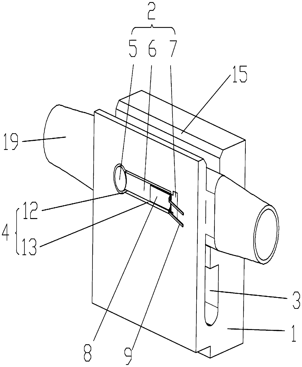
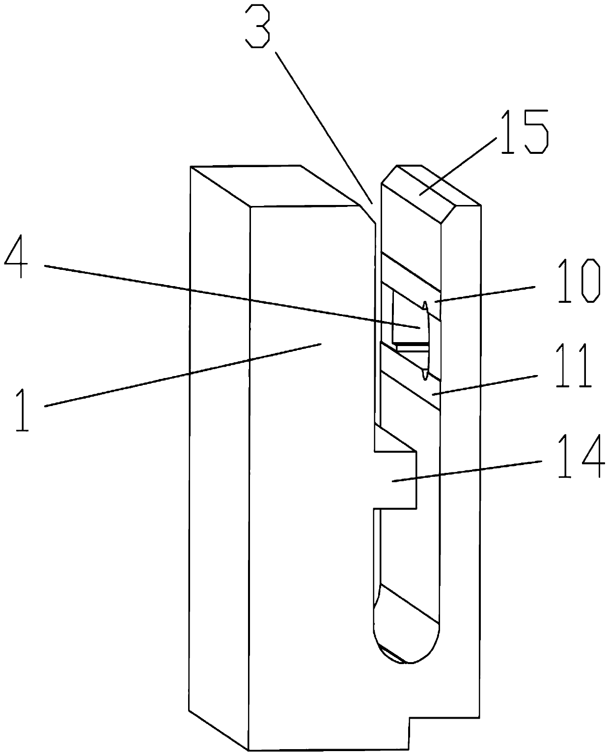
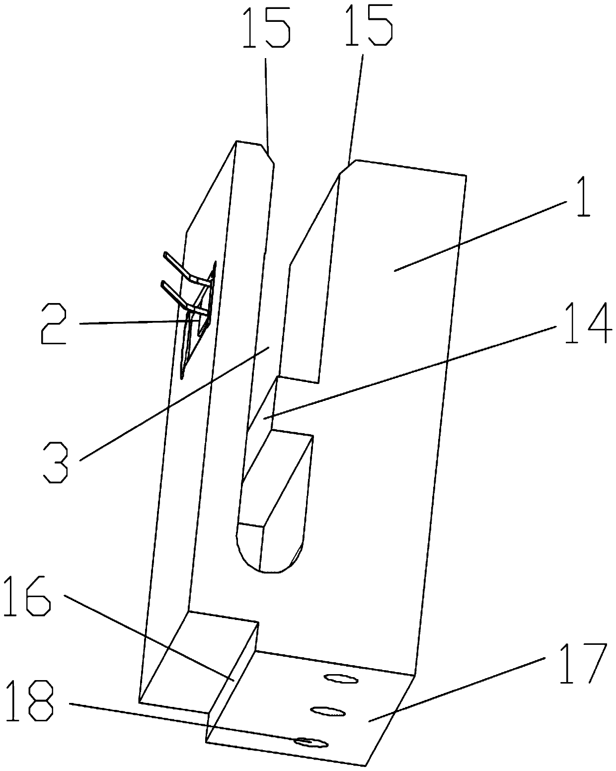
[0020] In order to facilitate a unified review of the various reference signs in the drawings of the specification, the unified description of the reference signs appearing in the drawings of the specification is as follows:

[0021] 1 is the fixed seat, 2 is the induction component, 3 is the infusion tube groove, 4 is the induction groove, 5 is the induction head, 6 is the induction arm, 7 is the induction fixed block, 8 is the strain gauge, 9 is the signal output line, 10 is the Upper support surface, 11 is the lower support surface, 12 is a round hole, 13 is a rectangular hole, 14 is a support platform, 15 is a chamfer, 16 is a positioning surface, 17 is a fixing surface, 18 is a screw hole, 19 is an infusion tube, 20 is the center of the outer wall of the infusion tube, 21 is the upper end of the outer wall of the infusion tube, and 22 ...


PUM


Abstract

The invention relates to an infusion tube pressure sensor, comprising a fixing seat and an induction component mounted on the fixing seat; the fixing seat is provided with an infusion tube groove andan induction groove, the induction groove is communicated with the infusion tube groove, an infusion tube passes through the infusion tube, the induction component is located in the induction groove,and the induction component comprises an induction head, a induction arm and an induction fixing block which are sequentially connected; the induction fixing block is fixed on an inner wall of one endof the induction groove, the induction head and the induction arm are both suspended in the induction groove, a strain gauge is arranged on the induction arm, a signal output line is arranged on thestrain gauge, the induction head and the induction arm are both in contact with an outer wall of the infusion tube, an inner wall of the infusion tube groove is provided with an upper support surfaceand a lower support which are in contact with an outer wall of the infusion tube, the upper support surface and the lower support surface are both arranged along the axial direction of the infusion tube, and the upper support surface and the lower support surface are separated at two ends of the induction groove. The infusion tube pressure sensor can measure the pressure of liquid inside the infusion tube and reduce a measurement error, and belongs to the technical field of infusion tube pressure sensors.

Description

technical field [0001] The invention relates to the technical field of pressure sensors, in particular to a pressure sensor for an infusion tube. Background technique [0002] During the infusion process, due to the random movement of the infusion site by the patient, the drug solution may seep into the subcutaneous area. If it is an ordinary gravity infusion, with the swelling of the infusion site and the increase of local pressure, the fluid infusion rate will gradually decrease or even stop. Usually, the infusion pump does not have a liquid medicine extravasation detection device, and when the liquid medicine extravasation occurs, the infusion will still be continued according to the set procedure. [0003] The pressure sensor currently used in the infusion pump is mainly composed of a cantilever load cell and a measuring head. The measuring head presses the infusion tube to sense the fluid pressure inside the infusion tube, and calculates and judges through the controll...

Claims


Application Information

Patent Timeline
Patent Type & Authority Applications(China)
IPC IPC(8): A61M5/168
CPCA61M5/16859A61M2205/15A61M2205/3331
Inventor 谢遨儒黄汉东沈雅谢斌
Owner 广州市便携医疗科技有限公司
Why Eureka
Try Eureka