
Cable suspending device

A suspension device, cable technology, applied in the direction of cable laying equipment, can solve the problem of time-consuming and laborious, and achieve the effect of rapid installation

Inactive Publication Date: 2019-04-26
张婉月
View PDF0 Cites 2 Cited by
  • Summary
  • Abstract
  • Description
  • Claims
  • Application Information

AI Technical Summary

Problems solved by technology

[0002] When installing cables, it is often necessary to temporarily suspend the cables. The current suspension method is to use pipe clips. During operation, the screws of the pipe clips need to be loosened with a screwdriver to install the cables, which is very time-consuming and laborious.

Method used


Image

  • Cable suspending device

Examples


Embodiment Construction

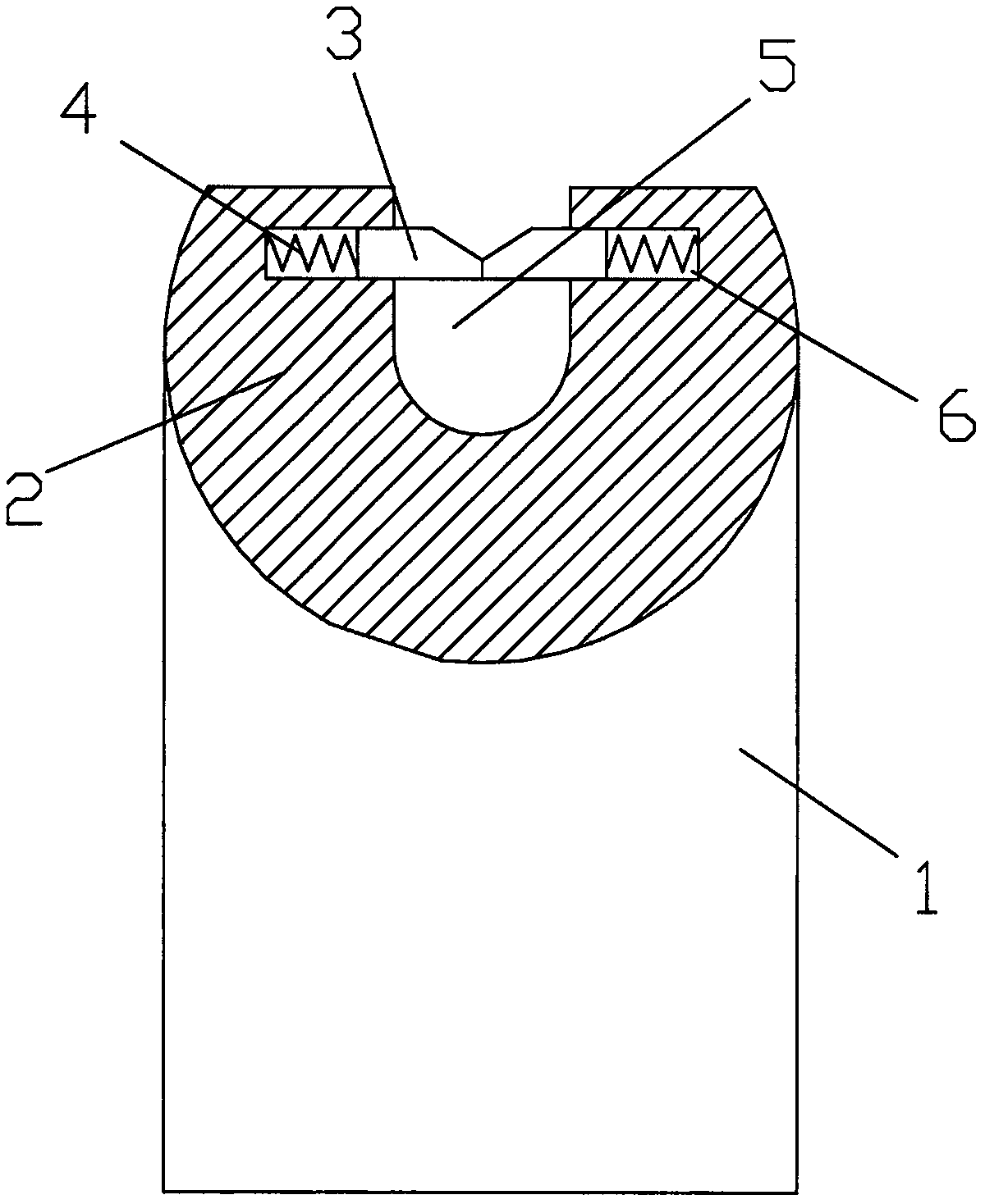
[0008] like figure 1 As shown, a cable suspension device includes a fixing seat 1, on which a pressing block 2 is arranged, and each notch 3 is provided in the center of the pressing block 2, and a counterbore 6 is respectively provided on both sides of the notch 3, A spring 4 and a jacking block 3 are arranged in the counterbore 6, and the two springs 4 push the two jacking blocks 3 to be close to each other, and an oblique opening is arranged at one end of the two jacking blocks 3 close to each other.

[0009] When in use, the cable can be snapped into the notch 3, and the cable can be fixed by two top blocks 3, so that the cable can be suspended conveniently, and the quick installation of the cable can be realized.


PUM


Abstract

The invention discloses a cable suspending device. The cable suspending device comprises a fixation base, a pressing block is arranged on the fixation base, a gap is formed in the center of the pressing block, and countersink holes are formed in the two sides of the gap respectively; springs and top blocks are arranged in the countersink holes, the two springs push the two top blocks to fit each other, and bevel ports are formed in the ends, close to each other, of the two top blocks. During use, a cable can be clamped into the gap, the two top blocks are utilized for fixing the cable, so thatthe cable is conveniently suspended, and then the cable is quickly installed.

Description

technical field [0001] The invention relates to a cable suspension device. Background technique [0002] When installing cables, it is often necessary to temporarily suspend the cables. The current suspension method is to use tube clamps. During operation, the screws of the tube clamps need to be loosened with a screwdriver to install the cables, which is very time-consuming and laborious. Contents of the invention [0003] The technical problem to be solved by the present invention is to provide a cable suspension device, which can easily suspend cables. [0004] In order to solve the above problems, the technical solution to be solved in the present invention is: a cable suspension device, including a fixing seat, a pressing block is arranged on the fixing seat, a gap is opened in the center of the pressing block, and there are A counterbore, a spring and a top block are arranged in the counterbore, two springs push the two top blocks to be close to each other, and an o...

Claims


Application Information

Patent Timeline
IPC IPC(8): H02G1/06
CPCH02G1/06
Inventor 张婉月
Owner 张婉月
Learn More