Cabinet door chuck

A chuck and cabinet door technology, which is applied to building fastening devices, wing leaf fastening devices, buildings, etc., can solve the problems of inconvenient use and achieve the effect of simple and convenient operation and avoid automatic closing

Inactive Publication Date: 2019-04-30
马克武
View PDF0 Cites 1 Cited by
  • Summary
  • Abstract
  • Description
  • Claims
  • Application Information

AI Technical Summary

Problems solved by technology

[0002] After the cabinet door is opened, the cabinet door needs to be temporarily positioned to prevent the cabinet door from being

Method used


Image

  • Cabinet door chuck

Examples


Embodiment Construction

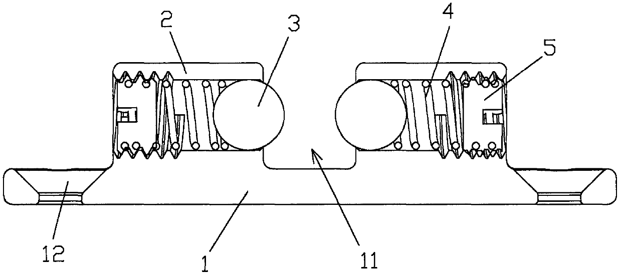
[0008] Such as figure 1 As shown, a cabinet door chuck includes a bottom plate 1, two sleeves 2 are arranged on the bottom plate 1, a spring 4, a steel ball 3 and a screw plug 5 are arranged in the sleeve 2, and the two ends of the spring 4 are respectively Against the steel ball 3 and the screw plug 5, one end of the steel ball 3 is exposed to the pipe sleeve 2 and is located in the gap 11 between the two pipe sleeves 2, and the two ends of the bottom plate 1 are provided with cones for installing countersunk screws. Shaped hole 12.

[0009] The protruding head on the cabinet door can be snapped into the gap 11 between the two steel balls 3, and the two steel balls 3 can position the protruding head to avoid automatic closing of the cabinet door, and the operation is simple and convenient.


PUM


Abstract

The invention discloses a cabinet door chuck which comprises a bottom plate, wherein two pipe sleeves are arranged on the bottom plate; springs, steel balls and plug screws are arranged in the pipe sleeves; two ends of the springs respectively pop up the steel balls and the plug screws; one ends of the steel balls are exposed out of the pipe sleeves and positioned in a gap between the two pipe sleeves; conical holes used for mounting countersunk screws are formed in two ends of the bottom plate. The raised head on the cabinet door can be clamped in the gap between the two pipe sleeves, the raised head can be positioned by the two steel balls, the cabinet door is avoided from being automatically closed, and the operation is simple and convenient.

Description

technical field [0001] The invention relates to a cabinet door chuck. Background technique [0002] After the cabinet door is opened, the cabinet door needs to be temporarily positioned to prevent the cabinet door from being automatically closed due to external force. The current fixing method uses a door plug to fix it, which is not very convenient to use. Contents of the invention [0003] The technical problem to be solved by the present invention is to provide a cabinet door chuck, which can position the cabinet door and avoid automatic closing of the cabinet door. [0004] In order to solve the above-mentioned problems, the technical solution to be solved in the present invention is: a kind of cabinet door chuck, including a bottom plate, two pipe sleeves are arranged on the bottom plate, a spring, a steel ball and a screw plug are arranged in the pipe sleeve, and the spring The two ends respectively lean against the steel ball and the screw plug. One end of the stee...

Claims


Application Information

Patent Timeline
IPC IPC(8): E05C17/02
CPCE05C17/02
Inventor 马克武
Owner 马克武
Why Eureka
Try Eureka