Supercharge Your Innovation With Domain-Expert AI Agents!

Self-locking type centrifugal pendulum device, and use of the type of centrifugal pendulum

A centrifugal pendulum and locking device technology, which is applied in the direction of rotation vibration suppression, vibration suppression adjustment, spring/shock absorber, etc., can solve the problem of increasing the number of startup processes, and achieve the effect of reducing the number of components and reducing the fluctuation of rotation speed

Pending Publication Date: 2019-04-30
FORD GLOBAL TECH LLC
View PDF3 Cites 0 Cited by
  • Summary
  • Abstract
  • Description
  • Claims
  • Application Information

AI Technical Summary

Problems solved by technology

Therefore, the number of startup processes increases

Method used


Image

  • Self-locking type centrifugal pendulum device, and use of the type of centrifugal pendulum
  • Self-locking type centrifugal pendulum device, and use of the type of centrifugal pendulum
  • Self-locking type centrifugal pendulum device, and use of the type of centrifugal pendulum

Examples


Embodiment Construction

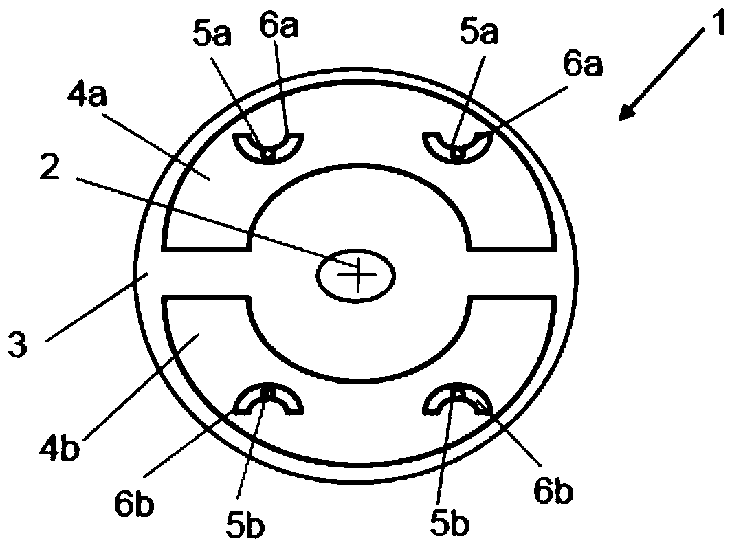
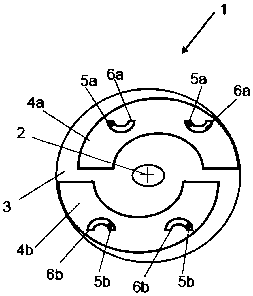
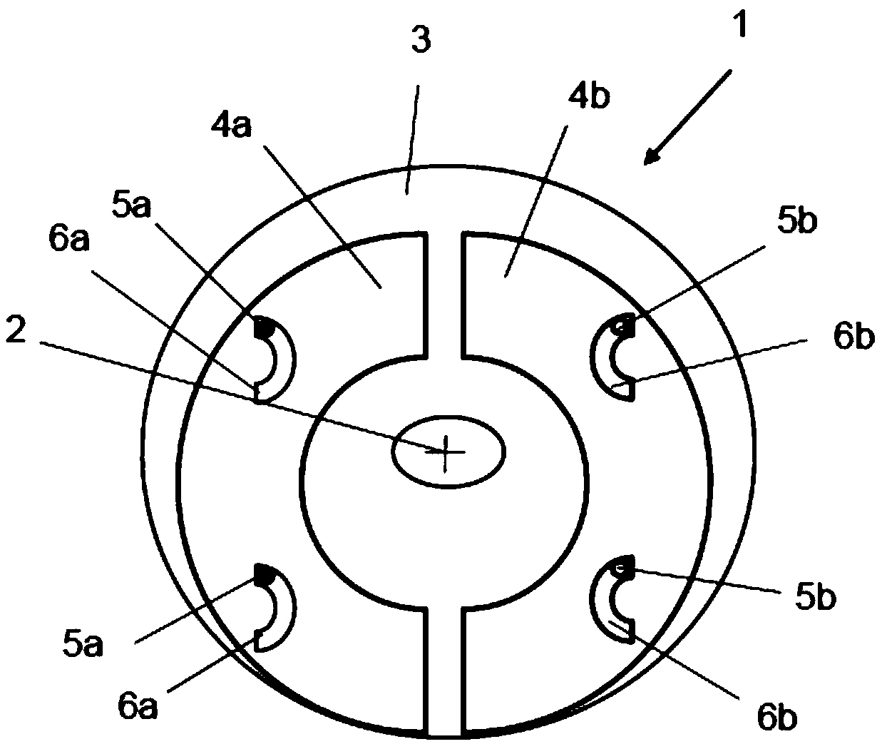
[0080] Figure 1a , 1b and 1c show a conventional centrifugal pendulum device 1 in side view and have already been discussed in connection with the prior art.

[0081] Figure 2a A first embodiment of the centrifugal pendulum device 1 according to the invention is shown schematically in side view, with the pendulums 4a, 4b fixed in a neutral center position. It is intended to discuss the differences with the centrifugal pendulum device 1 according to the prior art, for which reference is also made to Figure 1a , 1b and 1c and related descriptions. The same reference numerals have been used for the same parts.

[0082] Each pendulum 4a, 4b has two arcuate openings 6a, 6b with a convex surface towards the axis of rotation 2, so that the pendulum 4a, 4b can be fixed in an external position.

[0083] Figure 2a The centrifugal pendulum device 1 has two passive locking devices 7 which are self-controlled and utilize the centrifugal effect here.

[0084] In this case, each cr...


PUM


Abstract

A centrifugal pendulum device has a pendulum bob bracket which can rotate around a rotation axis, and is provided with a pendulum bob which is movable on the pendulum bob and is separated from the rotation axis. The pendulum bob has an arc-shaped opening. A roller pin of the pendulum bob bracket is connected with the arc-shaped opening, wherein each pendulum bob is provided with a passive self-controlled locking device. The passive self-controlled locking device comprises a centrifugal weight, a locking element and a spring element. The spring element and the locking element are arranged between the pendulum bob and the rotation axis in each condition. The spring element is preloaded so that when the pendulum bob bracket is stationary, the locking element functioned by the force of the spring element is utilized for applying a force in a radially outward direction on the pendulum bob and fixing the pendulum bob to an outside position. Furthermore along with increase of a rotatign speedncarrier of the pendulum bob bracket, when the rotation speed exceeds a preset rotation speed (ncarrier, fix), the spring element gradually deforms so that the locking element gradually releases thependulum bob.

Description

technical field [0001] The invention relates to a centrifugal pendulum device with at least one pendulum carriage rotatable about an axis of rotation and with at least two pendulums arranged displaceably on the pendulum carriage, Positioned opposite one another and spaced apart from the axis of rotation, the pendulums have arched openings into which the roller pins of the pendulum carriage engage, whereby the pendulums are kinematically positively guided. [0002] The invention also relates to the use of a centrifugal pendulum device of the type described. Background technique [0003] Vibration is an increasing concern in the construction and design of motor vehicles and internal combustion engines. In particular, an attempt was made to influence the noise produced by the internal combustion engine. The motivation for this development work stems from the recognition of the fact that consumer purchasing decisions are also jointly influenced by the noise of the internal com...

Claims


Application Information

Patent Timeline
Patent Type & Authority Applications(China)
IPC IPC(8): F16F15/14F16F15/133F16F15/131
CPCF16F15/131F16F15/1333F16F15/14F16F15/145
Inventor 乌利齐·伯特伦
Owner FORD GLOBAL TECH LLC
Features
  • R&D
  • Intellectual Property
  • Life Sciences
  • Materials
  • Tech Scout
  • Unparalleled Data Quality
  • Higher Quality Content
  • 60% Fewer Hallucinations
Learn More