An obstacle perspective method and an obstacle perspective device

A technology of obstacles and camera devices, applied in the direction of editing/combining graphics or text, instruments, characters and pattern recognition

Pending Publication Date: 2019-04-30
FU TAI HUA IND SHENZHEN +1
View PDF7 Cites 2 Cited by
  • Summary
  • Abstract
  • Description
  • Claims
  • Application Information

AI Technical Summary

Problems solved by technology

The disclosure of TWI267061 provides a method for superimposing and displaying multi-layer images in a s

Method used


Image

  • An obstacle perspective method and an obstacle perspective device
  • An obstacle perspective method and an obstacle perspective device
  • An obstacle perspective method and an obstacle perspective device

Examples


Embodiment Construction

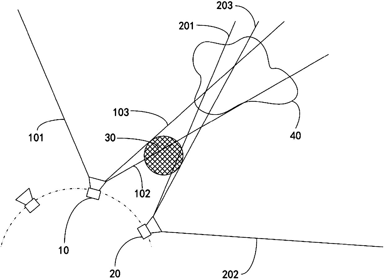
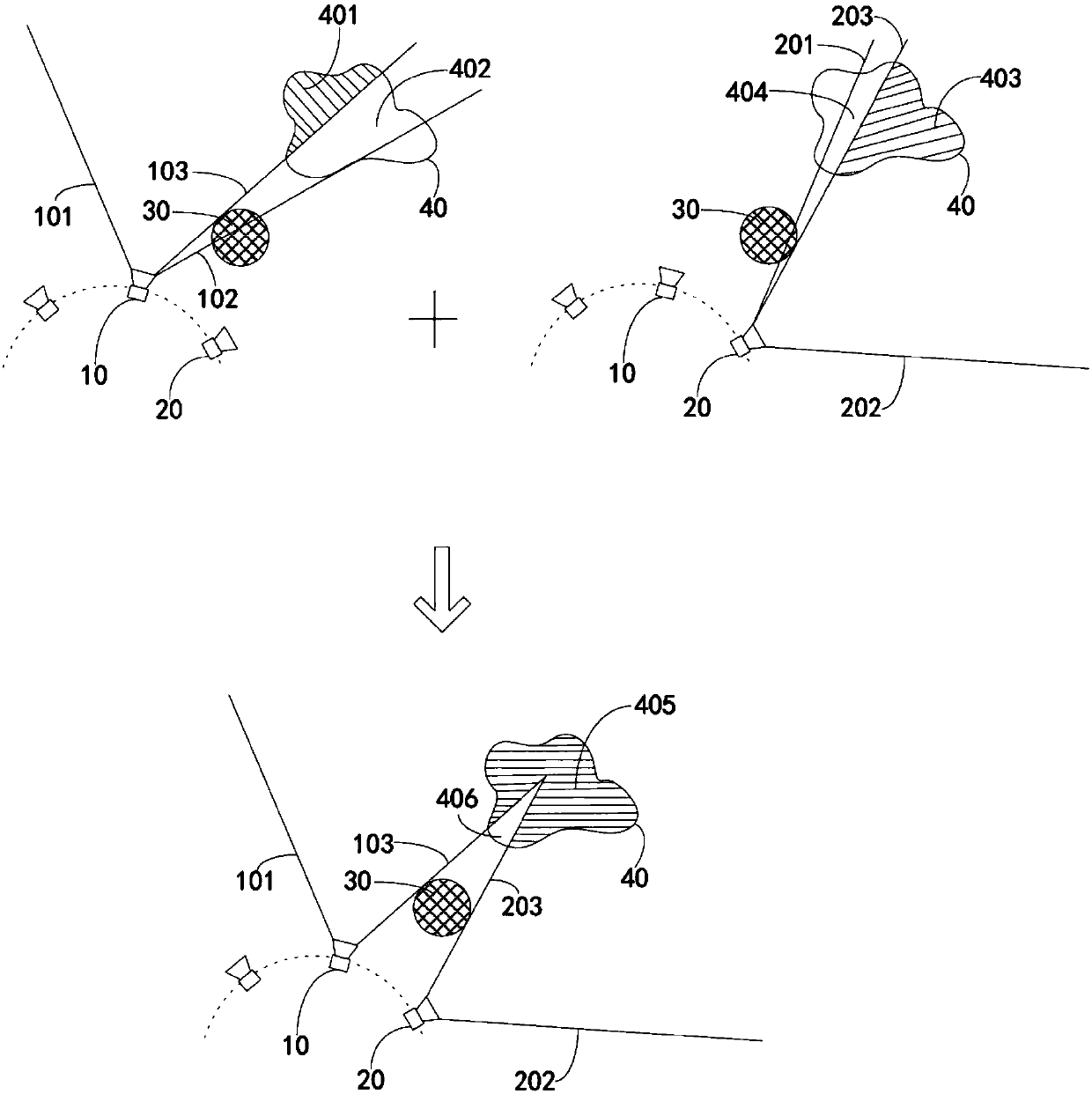
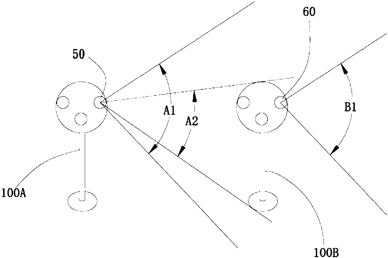
[0044] Such as figure 1 and figure 2 As shown, the obstacle see-through device includes a camera device (not shown in the figure) and a processing unit (not shown in the figure). Wherein, the camera device includes at least two groups of cameras, and the orientations of the at least two groups of cameras are different. In the following embodiments, the first camera 10 and the second camera 20 in the obstacle see-through device will be selected for illustration.

[0045] The viewing angles of the first camera 10 and the second camera 20 have overlapping areas. The signal output terminals of the first camera 10 and the second camera 20 are connected to a processing unit, and the processing unit may be a microprocessor. After receiving two sets of imaging information from the first camera 10 and the second camera 20, the processing unit fuses the two sets of imaging information to form panoramic information of a predetermined area. The panoramic information here can be under...


PUM


Abstract

The invention discloses an obstacle perspective method. The obstacle perspective method comprises the following steps: collecting at least two images partially shielded by a predetermined obstacle from at least two different visual angles; deleting the part, shielded by the obstacle, in the at least two images to generate at least two reserved images; determining a splicing position of the at least two reserved images; and splicing the at least two reserved images. The invention further discloses a corresponding obstacle perspective device. The invention discloses an obstacle perspective method and an obstacle perspective device, and aims to reduce or eliminate a visual field blind area caused by an obstacle.

Description

technical field [0001] The invention relates to an obstacle perspective method and an obstacle perspective device. Background technique [0002] In the presence of obstacles, it is often easy to form a blind area of ​​vision, and the observer or the shooting device cannot obtain the part of the vision blocked by the obstruction, and thus cannot obtain a complete picture. For example, the pillar between the windshield and the front door of the car is called the A-pillar. The A-pillar will block the driver's line of sight during driving, thus causing a visual blind spot. The existence of the A-pillar blind spot is one of the important causes of traffic accidents. The inconvenience of sight blocking is more obvious especially when the driver is turning or changing lanes. Therefore, the narrower the A-pillar, the better, and the A-pillar supports the front of the car. The internal weight requires a certain strength, which creates a contradiction between the inability to elimina...

Claims


Application Information

Patent Timeline
IPC IPC(8): G06T11/60G06K9/00
CPCG06T11/60G06V20/58
Inventor 王蕙雯何其勋李学文辛怡德郭俊彦
Owner FU TAI HUA IND SHENZHEN
Why Eureka
Try Eureka