Vertical automobile exhaust gas remote sensing monitoring device

A technology for vehicle exhaust and remote sensing monitoring, which is applied to measurement devices, instruments, scientific instruments, etc., can solve the problems of insufficient protection of detection devices and inconvenient angle adjustment, and achieve the effect of avoiding bump damage and convenient use.

Pending Publication Date: 2019-05-03
REED XINXIANG ROAD INC
0 Cites 1 Cited by

AI-Extracted Technical Summary

Problems solved by technology

[0005] In order to solve the above problems in the prior art, the present invention provides a vertical vehicle exhaust remote sensing monitoring device, which s...

Method used

The working principle of the present invention: the mobile housing 2 slides and connects the fixed housing 1 through the sliding rail 9, and the mobile housing 2 can be protected during transportation to avoid the bump damage of the components in the mobile housing 2. It can be fixed by the cooperation of the limit bolt 18 and the limit groove 8. The remote sensing exhaust gas detection device 3 can carry out remote sensing detection of the automobile exhaust gas. When the detection exhaust gas exceeds the standard, the processor 6 can be used to control the camera 5 and upload the vehicle license plate. One side of the adjustment block 10 is provided with...

Abstract

The invention discloses a vertical automobile exhaust gas remote sensing monitoring device which comprises a fixed casing body, a remote sensing exhaust gas detecting device, a camera and a processor.The inside fixed casing body is movably connected with a movable casing body through a sliding rail. The open end of the movable casing body is connected with a protective cover. One side of the movable casing body is connected with the remote sensing exhaust gas detecting device. One side of the movable casing body is connected with the camera. The device provided by the invention has the advantages that the movable casing body is slidably connected with the fixed casing body through the sliding rail; the movable casing body can be protected during transportation to prevent bump damage of components in the movable casing body; the remote sensing exhaust gas detecting device can carry out remote sensing detection on automobile exhaust gas; when the fact that the exhaust gas exceeding thestandard is detected, the camera is controlled by the processor to photograph and upload a license plate; clamp teeth are arranged on one side of an adjusting block; and a fastening bolt is engaged with the corresponding clamp teeth on one side of the connecting rod to adjust tilting angle, so that the device is easier to use.

Application Domain

Technology Topic

Image

  • Vertical automobile exhaust gas remote sensing monitoring device
  • Vertical automobile exhaust gas remote sensing monitoring device
  • Vertical automobile exhaust gas remote sensing monitoring device

Examples

  • Experimental program(1)

Example Embodiment

[0023] In order to better explain the present invention and facilitate understanding, the following describes the present invention in detail through specific embodiments in conjunction with the accompanying drawings.
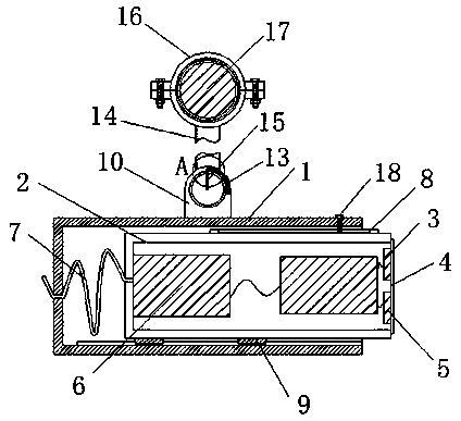
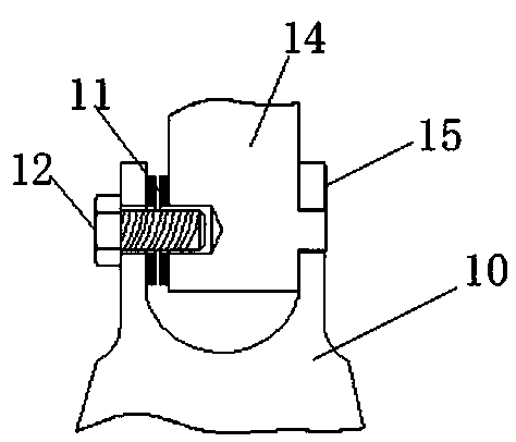
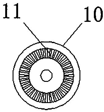
[0024] See Figure 1-4 , The present invention provides a technical solution: a vertical vehicle exhaust remote sensing monitoring device, which includes: a fixed housing 1, a remote sensing exhaust detection device 3, a camera 5 and a processor 6, and the fixed housing 1 passes through a sliding rail 9 and The mobile housing 2 is movably connected, the open end of the mobile housing 2 is connected to the protective cover 4, the remote sensing exhaust gas detection device 3 is connected to the mobile housing 2 side, the camera 5 is connected to the mobile housing 2 side, and the processor 6 is installed in the mobile housing 2 , The processor 6 is connected to the external port through the bus 7, the upper end of the mobile shell 2 is connected to the limit slot 8, the limit slot 8 is connected to the limit bolt 18, the upper end of the fixed shell 1 is connected to the adjustment block 10, the adjustment block 10 A clamping tooth 11 is provided on the inner side, and an angle plate 13 is provided on the outer side of the adjusting block 10. The adjusting block 10 is connected to the connecting rod 14 by a fastening bolt 12. The connecting rod 14 is connected to the indicator pin 15 at one side and one end of the connecting rod 14 It is connected to the cross beam 17 by a fixing ring 16.
[0025] Further, the fixed housing 1 is hollow, the movable housing 2 is movably connected with the fixed housing 1 through a sliding rail 9, and the movable housing 2 can move in a horizontal direction.
[0026] In this embodiment, the movable housing 2 is slidably connected to the fixed housing 1 through a sliding rail 9, so that the movable housing 2 can be protected during transportation, so as to avoid collision damage to the components in the movable housing 2.
[0027] Further, one end of the mobile casing 2 is connected to the bus 7, and the length of the bus 7 is greater than the horizontal movement stroke of the mobile casing 2.
[0028] In this embodiment, the bus 7 will not be pulled when the movable housing 2 moves in the horizontal direction.
[0029] Further, the remote sensing exhaust gas detection device 3, the camera 5 and the processor 6 are electrically connected, and the remote sensing exhaust gas detection device 3 can remotely detect the content of the exhaust gas emitted by the automobile.
[0030] In this embodiment, the remote sensing exhaust gas detection device 3 can perform remote sensing detection of automobile exhaust gas, and when the exhaust gas exceeds the limit, the processor 6 can control the camera 5 to upload the license plate of the automobile.
[0031] Further, the adjustment block 10 is a U-shaped arrangement, one side of the adjustment block 10 is provided with a threaded hole matching the fastening bolt 12, and one side is provided with a through hole for clamping with the connecting rod 14.
[0032] In this embodiment, the adjusting block 10 can be connected to the connecting rod 14 by a fastening bolt 12.
[0033] Further, the adjusting block 10 and the connecting rod 14 are provided with corresponding clamping teeth 11 on one side, and the clamping teeth 11 mesh with each other when they are attached.
[0034] In this embodiment, different inclination angles can be adjusted by the engagement of the clamping teeth 11, and the angle can be adjusted according to different usage occasions.
[0035] Further, the fixing ring 16 is arranged separately, and the fixing ring 16 is connected by symmetrical fixing bolts.
[0036] In this embodiment, the fixed ring 16 is arranged separately to facilitate installation and connection with the beam 17.
[0037] The working principle of the present invention: the movable housing 2 is slidably connected to the fixed housing 1 through the sliding rail 9, which can protect the movable housing 2 during transportation, avoid the collision and damage of the components in the movable housing 2, and can pass through The limit bolt 18 cooperates with the limit slot 8 for fixing. The remote sensing exhaust detection device 3 can remotely detect automobile exhaust. When the exhaust exceeds the standard, the processor 6 can control the camera 5 to upload the license plate of the automobile. One side is provided with a clamping tooth 11, and the fastening bolt 18 is engaged with the corresponding clamping tooth 11 on the side of the connecting rod 14 to adjust the inclination angle. The connecting rod 14 and the cross beam 17 are connected by a plurality of bolts, which is convenient for installation.
[0038] It should be noted that in this article, relational terms such as first and second are only used to distinguish one entity or operation from another entity or operation, and do not necessarily require or imply one of these entities or operations. There is any such actual relationship or order between. Moreover, the terms "include", "include" or any other variants thereof are intended to cover non-exclusive inclusion, so that a process, method, article or device including a series of elements not only includes those elements, but also includes those that are not explicitly listed Other elements of, or also include elements inherent to this process, method, article or equipment. Without more restrictions, the element defined by the phrase "including a reference structure" does not exclude the existence of other identical elements in the process, method, article, or equipment including the element.
[0039] Although the embodiments of the present invention have been shown and described, those of ordinary skill in the art can understand that various changes, modifications, and substitutions can be made to these embodiments without departing from the principle and spirit of the present invention. And variations, the scope of the present invention is defined by the appended claims and their equivalents.

PUM

no PUM

Description & Claims & Application Information

We can also present the details of the Description, Claims and Application information to help users get a comprehensive understanding of the technical details of the patent, such as background art, summary of invention, brief description of drawings, description of embodiments, and other original content. On the other hand, users can also determine the specific scope of protection of the technology through the list of claims; as well as understand the changes in the life cycle of the technology with the presentation of the patent timeline. Login to view more.

Similar technology patents

Roll type electrodialyzer

PendingCN114849477AEasy to carryAvoid bump damageGeneral water supply conservationElectrodialysisElectrodialysisStructural engineering
Owner:ZHEJIANG LVCHUANG BIOTECHNOLOGY CO LTD

Portable boiler wastewater component detection device

PendingCN114236070AAvoid bump damageEasy to grab and useTesting waterLinear motorElectric machine
Owner:刘杰

Classification and recommendation of technical efficacy words

  • Easy to use
  • Avoid bump damage

Laser assisted total joint arthroplasty

InactiveUS20090234360A1Easy to useNon-surgical orthopedic devicesSurgical sawsLaser assistedLaser guidance
Owner:ALEXANDER VLADIMIR

System, method, and apparatus for settlement for participation in an electric power grid

ActiveUS8583520B1Communication securityEasy to useLevel controlCoin-freed apparatusNetwork managementGrid operator
Owner:CAUSAM ENERGY INC

Portable high vegetable and fruit picking device

ActiveCN108076819AAvoid bump damagePicking devicesEngineeringPower output
Owner:HEXIAN LVYUAN VEGETABLE PLANTATION CO LTD

Lubricating oil-way of engine cylinder assembly

InactiveCN1786449AAvoid bump damageBeautiful structural designCylinder headsCylindersCylinder blockMotor oil
Owner:CHERY AUTOMOBILE CO LTD

Rainproof and sunshield multifunctional two-wheeled vehicle mobile phone holder

InactiveCN107813889AEnsure electricity safetyAvoid bump damageArticle supporting devicesOther supporting devicesElectrical and Electronics engineeringMobile phone
Owner:湖南海得利网络科技有限公司
Why Eureka
Try Eureka