Fault Detection Method of Consumable Parts in Plasma Arc Spray Gun

A plasma arc and fault detection technology, which is applied in the direction of plasma, electrical components, and measuring electronics, can solve the problems of unfavorable fault characteristic signal acquisition, affecting detection stability, and practical difficulties, so as to avoid further expansion of faults and stabilize the detection effect Reliable, avoid excessive loss effect

Active Publication Date: 2021-09-03
CHANGZHOU JIUSHENG WELDING EQUIP
View PDF8 Cites 0 Cited by
  • Summary
  • Abstract
  • Description
  • Claims
  • Application Information

AI Technical Summary

Problems solved by technology

[0004] Defects of the method of "Fault Event Detection in Plasma Arc Spray Gun": the detection is easily interfered by high-intensity electromagnetic disturbance when the arc is transferred, and it is easy to make the detection protection allergic and affect the stability of the detection; the operating current is often controlled by a constant current feedback control circuit Control, the current has high stability and is not easy to fluctuate. If the operating current is used as the detection object, it is not easy to detect the failure of consumable parts; the operating voltage of the plasma arc spray gun is often called the arc voltage. There will be a high voltage of more than several thousand volts during arc ignition and arc rotation, and the signal sampling is dangerous. Even in normal operation, there are large voltage fluctuations, which is not conducive to the acquisition of fault characteristic signals.
[0006] Defects of the method of "System and Method for Detecting Nozzle and Electrode Loss": the stability of this method is difficult to guarantee
On the one hand, the electrode accessories have a certain dimensional tolerance, and the arc voltage of each accessory is also different; secondly, the surface of the workpiece to be processed is not necessarily flat, and the height between the arc spray gun and the workpiece will change continuously during operation, resulting in constant arc voltage. change; and, again, how are new and old accessories perceived to differ? How to fix it? There are great difficulties in practical

Method used


Image

  • Fault Detection Method of Consumable Parts in Plasma Arc Spray Gun
  • Fault Detection Method of Consumable Parts in Plasma Arc Spray Gun
  • Fault Detection Method of Consumable Parts in Plasma Arc Spray Gun

Examples


Embodiment Construction

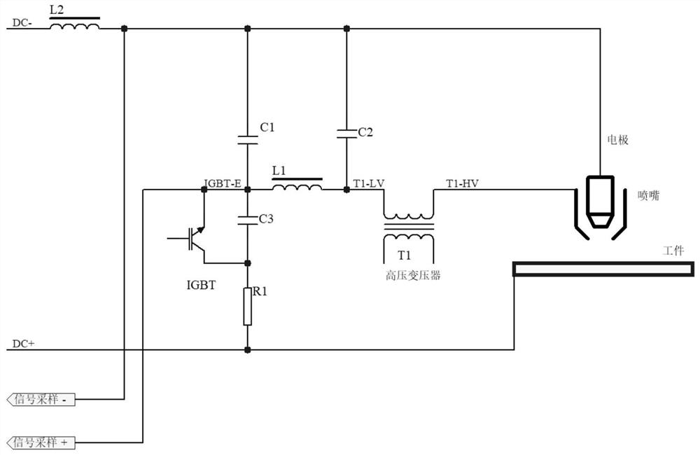
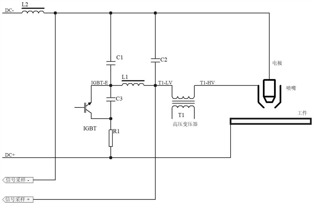
[0032] The present invention will be described in detail in conjunction with accompanying drawing now. This figure is a simplified schematic diagram only illustrating the basic structure of the present invention in a schematic manner, so it only shows the components relevant to the present invention.

[0033] like figure 1 and figure 2 As shown, a method for detecting faults of consumable parts in a plasma arc spray gun of the present invention, the method includes: during the operation of the plasma arc spray gun, continuously detect the E pole voltage (IGBT-E) of the arc-turning IGBT and the high-voltage arc ignition transformer At least one of the low-voltage terminal voltages (T1-LV);

[0034] Determining at least one of the E pole voltage of the arc-turning IGBT and the low-voltage terminal voltage of the high-voltage arc-igniting transformer the number N of sudden changes in the voltage within the preset time period T, and calculating the voltage occurrence within the...


PUM


Abstract

The invention provides a method for detecting faults of consumable parts in a plasma arc spray gun. During the operation of the plasma arc spray gun, the method continuously detects at least one of the voltage at the E pole of the arc-turning IGBT or the voltage at the low-voltage end of the high-voltage arc ignition transformer. The number of sudden changes in the detection voltage within a certain period of time can be used to determine the failure of consumable parts in the plasma arc spray gun. This method can timely detect the failure of consumable parts in the operation of the plasma arc spray gun and stop and warn, which can avoid further expansion of the fault, so that the production will not stop due to the scrapping of the spray gun, reduce economic losses, and also help to avoid excessive wear of consumable parts leading to processing decline in quality.

Description

technical field [0001] The invention relates to the field of plasma arc and application technology, in particular to a method for detecting faults of consumable parts in a plasma arc spray gun. Background technique [0002] Consumable parts often fail in the operation of plasma arc spray gun. If there is no effective method for detecting the fault of consumable parts in plasma arc spray gun, the fault cannot be found in time and the shutdown will result in a decrease in the processing quality of the workpiece, which will further lead to the expansion of the fault , Even the spray gun body is scrapped, causing economic losses, increasing production costs, and production halts affecting production efficiency. Therefore, it is necessary to detect and discover the failure of consumable parts in time, and to shut down and warn. In addition, when using unmatched consumable parts by mistake, the failure phenomenon will also appear in advance. Therefore, a method for detecting the...

Claims


Application Information

Patent Timeline
Patent Type & Authority Patents(China)
IPC IPC(8): G01R31/00H05H1/00H05H1/32
Inventor 杨京华王晓钱俊华涂有波
Owner CHANGZHOU JIUSHENG WELDING EQUIP
Why Eureka
Try Eureka