
Air conditioning ducts for rail vehicles and rail vehicles

A technology for air-conditioning ducts and rail vehicles, which is applied in the field of rail vehicles, and can solve problems such as uneven air outlet, difficulty in setting up a static pressure chamber, and large installation space, and achieve the effects of avoiding poor comfort, uniform air outlet, and favorable air outlet

Active Publication Date: 2021-06-18
BYD CO LTD
View PDF0 Cites 0 Cited by
  • Summary
  • Abstract
  • Description
  • Claims
  • Application Information

AI Technical Summary

Problems solved by technology

[0002] The air-conditioning duct of the rail vehicle is long, and the distance between the front and rear of the car and the air inlet is inconsistent, and the problem of uneven air outlet is very likely to occur
In related technologies, in order to solve the aforementioned problems, a larger static pressure chamber is usually provided, but the static pressure chamber needs to occupy a large installation space, especially for compact models, it is difficult to install a static pressure chamber
[0003] In addition, if an air outlet hole is provided on the bottom plate of the air-conditioning duct directly opposite the air inlet, the air outlet at this place will be too large, which will affect the user experience. In related technologies, some rail vehicles directly cancel the air outlet hole at this place, resulting in The comfort level here is poor, there is room for improvement

Method used


Image

  • Air conditioning ducts for rail vehicles and rail vehicles
  • Air conditioning ducts for rail vehicles and rail vehicles
  • Air conditioning ducts for rail vehicles and rail vehicles

Examples


Embodiment Construction

[0025] Embodiments of the present invention are described in detail below, examples of which are shown in the drawings, wherein the same or similar reference numerals designate the same or similar elements or elements having the same or similar functions throughout. The embodiments described below by referring to the figures are exemplary only for explaining the present invention and should not be construed as limiting the present invention.

[0026] In describing the present invention, it should be understood that the terms "center", "longitudinal", "transverse", "length", "width", "thickness", "upper", "lower", "front", " Back", "Left", "Right", "Vertical", "Horizontal", "Top", "Bottom", "Inner", "Outer", "Clockwise", "Counterclockwise", "Axial", The orientation or positional relationship indicated by "radial", "circumferential", etc. is based on the orientation or positional relationship shown in the drawings, and is only for the convenience of describing the present invent...


PUM


Abstract

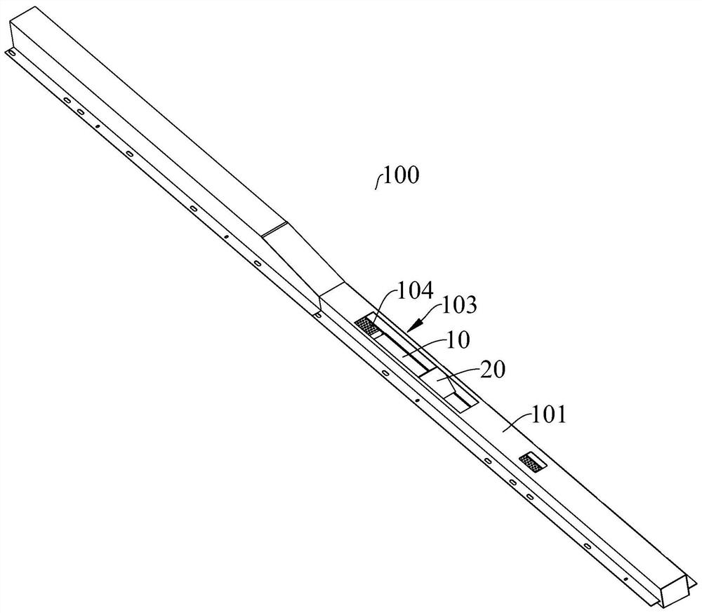
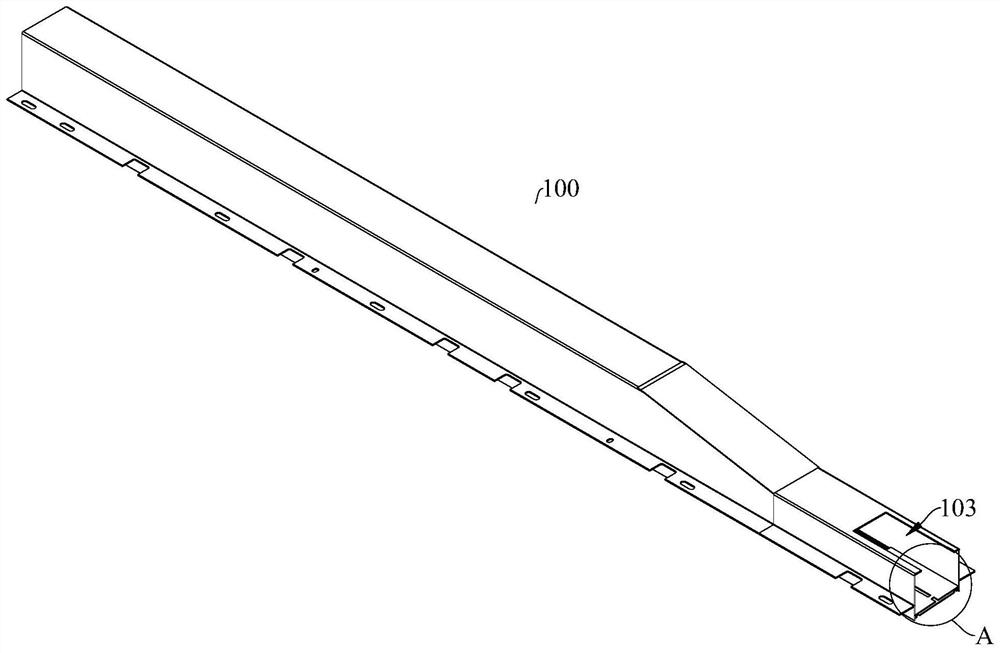
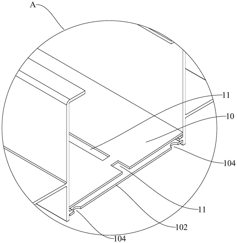
The invention discloses an air-conditioning duct of a rail vehicle and a rail vehicle. The air inlet of the air-conditioning duct is arranged on the first wall of the air-conditioning duct, and a plurality of outlet holes of the air-conditioning duct are arranged on the first wall of the air-conditioning duct. The second wall of the air-conditioning duct, the part of the plurality of air outlet holes and the air inlet are located at the same position in the length direction of the air-conditioning duct, and the air-conditioning duct is provided with a A slow-flow plate with holes opposite to each other, the slow-flow plate is spaced apart from the second wall, and the ventilation holes on the slow-flow plate are arranged in a staggered manner from the air outlet holes. The air-conditioning air duct of the present invention can prevent the airflow coming in from the air inlet from being directly discharged from the air outlet by setting the slow flow plate, thereby reducing the air output at the air inlet, and avoiding the excessive air volume here that causes poor comfort below , conducive to uniform wind.

Description

technical field [0001] The invention belongs to the technical field of vehicle manufacturing, and in particular relates to an air-conditioning air duct of a rail vehicle and a rail vehicle having the air-conditioning air duct. Background technique [0002] The air-conditioning duct of the rail vehicle is long, and the distance between the front and rear of the car and the air inlet is inconsistent, and the problem of uneven air outlet is very likely to occur. In the related art, in order to solve the aforementioned problems, a larger static pressure chamber is usually provided, but the static pressure chamber needs to occupy a large installation space, especially for compact vehicles, it is difficult to install the static pressure chamber. [0003] In addition, if an air outlet hole is provided on the bottom plate of the air-conditioning duct directly opposite the air inlet, the air outlet at this place will be too large, which will affect the user experience. In related tec...

Claims


Application Information

Patent Timeline
Patent Type & Authority Patents(China)
IPC IPC(8): B61D27/00
Inventor 叶云飞李卢军龙启博
Owner BYD CO LTD
Learn More