Adjustable upper limb arm bracket

An adjustable arm technology, applied in the field of medical equipment, can solve problems such as dumping injuries, inflexible use, and easy to feel fatigue, and achieve the effects of easy installation and disassembly, good fixing effect, and guaranteed fixation

Pending Publication Date: 2019-05-10
JIANGSU CHENGKANG MEDICAL EQUIP CO LTD
View PDF4 Cites 1 Cited by
  • Summary
  • Abstract
  • Description
  • Claims
  • Application Information

AI Technical Summary

Problems solved by technology

Difficulty adjusting the angle and direction will cause the gravity on the arm to be unable to be balanced and adjusted during training. It is not flexible enough to use, and it also makes the patient's physical exertion serious and easy to feel fatigued.
In addition, if the force is not well balanced during training, it is prone to various uncontrollable free swings, which will lead to unpredictable falling injuries of the patient or damage to other surrounding objects by touching, which cannot meet the rehabilitation treatment that needs to adjust the angle of the arm. Therefore, urgently need those skilled in the art to design a kind of novel arm support structure

Method used


Image

  • Adjustable upper limb arm bracket
  • Adjustable upper limb arm bracket
  • Adjustable upper limb arm bracket

Examples


Embodiment 1

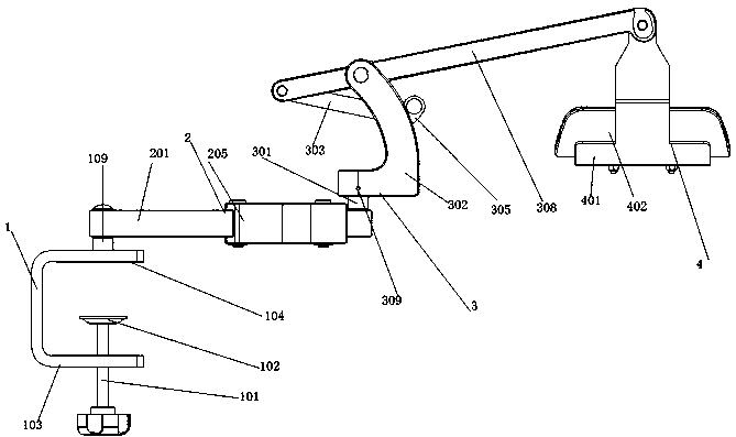
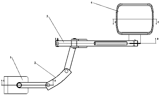
[0023] Embodiment 1: An adjustable upper limb arm support, including a fixed seat assembly 1, a triple lever assembly 2, an adjustable lever assembly 3 and a bracket assembly 4, the upper end of the fixed seat assembly 1 is provided with a triple lever assembly 2 and An adjustable lever assembly 3 is provided at one end of the three-linked lever assembly 2 and is rotatably connected with it, and a bracket assembly 4 is provided at the other end of the adjustable lever assembly 3 and is rotatably connected with it.

Embodiment 2

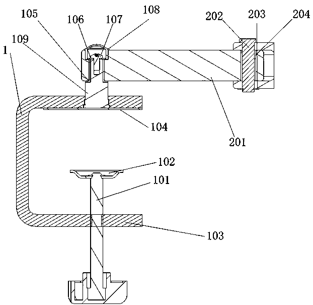
[0024]Embodiment 2: The fixing seat assembly 1 includes a push rod 101, a top cap 102, a fixing seat 103, a protection pad 104, a primary bearing 105, a flat washer 106, a cross recessed pan head screw 107, a blocking cover 108 and a primary fixing rod 109 , the push rod 101 passes through the threaded hole at one end of the fixing seat 103, the top cap 102 is fixed on the top of the push rod 101 through a pan head screw, the fixing seat 103 has a U-shaped structure, and the fixing seat 103 is passed through the push rod 101. The top cap 102 is fixed on the desktop, so that the fixing effect between the desktop and the fixing seat is good. The contact part of the fixing seat 103 and the desktop is bonded with a protective pad 104, which reduces the extrusion force of the top cap on the desktop. The fixed rod 109 is arranged on the upper end of the fixed base 103 and is fixedly connected with it as a hanging platform, which is convenient for installation and disassembly, and ens...

Embodiment 3

[0025] Embodiment 3: The three-link lever assembly 2 includes a straight connecting rod 201, a primary hinge pin 202, a primary E-shaped snap spring 203, a secondary bearing 204, and a curved connecting rod 205. The straight connecting rod 201 is provided with a positioning installation hole, the primary bearing 105 is located in the positioning installation hole, the straight connecting rod 201 and the primary fixed rod 109 are rotationally connected through the primary bearing 105, and one end of the straight connecting rod 201 is provided with a curved connecting rod 205 and passes through a The primary hinge pin 202 is linked, the secondary bearing 204 is sleeved on the primary hinge pin 202, the secondary bearing 204 and the primary hinge pin 202 are sleeved with a primary E-type snap ring 203, and the primary hinge The pin 202 is matched with the first-stage E-shaped clip spring 203. Through the connection and cooperative use of the above-mentioned components, the free ro...


PUM


Abstract

The invention discloses an adjustable upper limb arm bracket. The arm bracket comprises a fixed seat component, a three connecting lever component, an adjustable lever component and a bracket component, wherein the three connecting lever component is arranged on the upper end of the fixed seat component and is rotatably connected with the fixed seat component; the adjustable lever component is arranged on the upper end of the three connecting lever component and is rotatably connected with the three connecting lever component; the bracket component is arranged on the upper end of the adjustable lever component and is rotatably connected with the adjustable lever component; and the adjustable lever component comprises a secondary fixed rod, a lever seat, a pull rod, a pull ring and a lever;the secondary fixed rod is fixed in the lever seat; the lever is arranged on the upper end of the lever seat; the pull rod is arranged on one end of the lever; the lever seat and the lever, the leverand the pull rod and the pull rod and the pull ring are respectively connected by secondary hinge pins; tertiary bearings sleeve on the secondary hinge pins; and the pull ring and the lever seat arefixedly connected by a bayonet. The arm bracket disclosed by the invention has the beneficial effects that the angle and the direction can be adjusted to balance the gravity force on an arm during training; the arm bracket is very flexible in use and high in structural strength; and the comfort feeling of a patient in rehabilitation training is improved.

Description

technical field [0001] The invention relates to the technical field of medical devices, in particular to a height-adjustable arm support suitable for rehabilitation treatment. Background technique [0002] The current conventional arm support is only a simple support, the range of motion is small, and the height cannot be adjusted. Difficulty adjusting the angle and direction will lead to the inability to balance the gravity on the arms during training, and the use is not flexible enough, which also makes the patient's physical exertion serious and easy to feel fatigued. In addition, if the force is not well balanced during training, various uncontrollable free swings will easily occur, which will lead to unpredictable falling injuries of the patient or damage to other surrounding objects by touching, which cannot meet the rehabilitation treatment that needs to adjust the arm angle. Therefore, those skilled in the art are badly in need of designing a novel arm support struc...

Claims


Application Information

Patent Timeline
Patent Type & Authority Applications(China)
IPC IPC(8): A63B23/12A63B23/16A63B22/00A63B21/00
Inventor 汪贵祥袁长岭
Owner JIANGSU CHENGKANG MEDICAL EQUIP CO LTD
Why Eureka
Try Eureka