Quick die changing mechanism and die changing method

A fast, mold-based technology, applied in the field of stamping mold change, can solve the problems of inability to adapt to high-efficiency conversion products, long time-consuming mold change, low labor intensity, etc., to meet the requirements of time-consuming mold change, short mold change time, The effect of low labor intensity

Active Publication Date: 2019-05-21
机械科学研究院浙江分院有限公司
View PDF13 Cites 6 Cited by
  • Summary
  • Abstract
  • Description
  • Claims
  • Application Information

AI Technical Summary

Problems solved by technology

[0003] The purpose of the present invention is to overcome the existing problems of long time-consuming and labor-intensive mold change, which cannot meet the needs of high-efficiency product conversion in an automated production line with multiple stamping equipment, and provide a mold-changing time-consuming, labor-intensive Small, fast mold change mechanism and mold change method that meet the needs of high-efficiency product conversion in an automated production line with multiple stamping equipment

Method used


Image

  • Quick die changing mechanism and die changing method
  • Quick die changing mechanism and die changing method
  • Quick die changing mechanism and die changing method

Examples


Embodiment Construction

[0021] The present invention will be further described below in conjunction with the accompanying drawings.

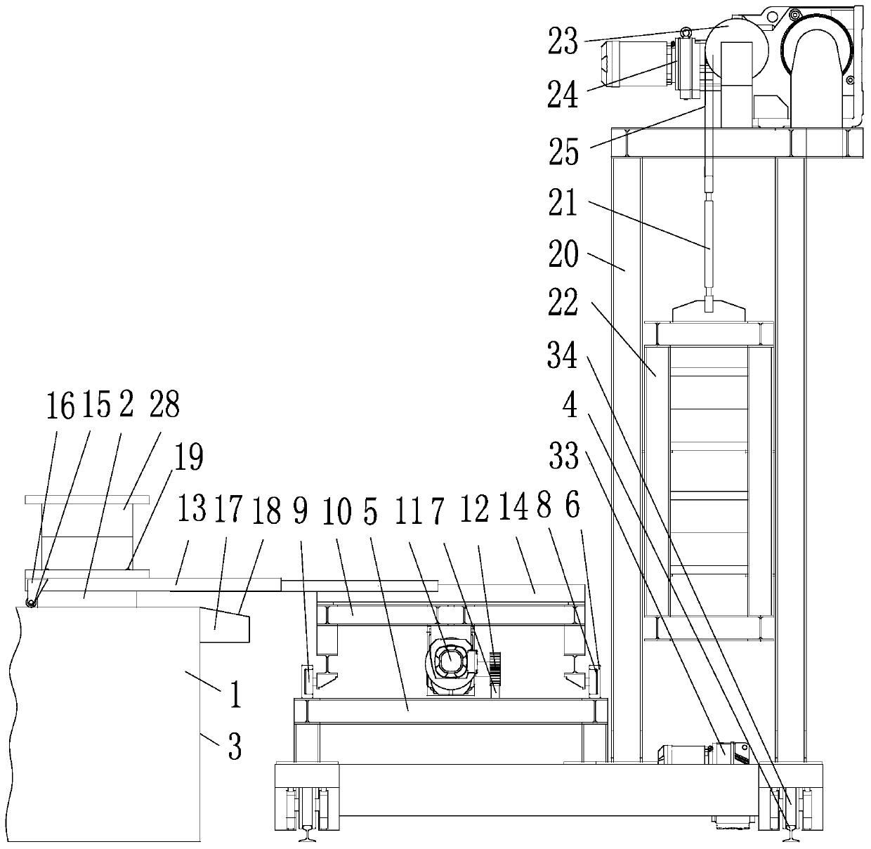
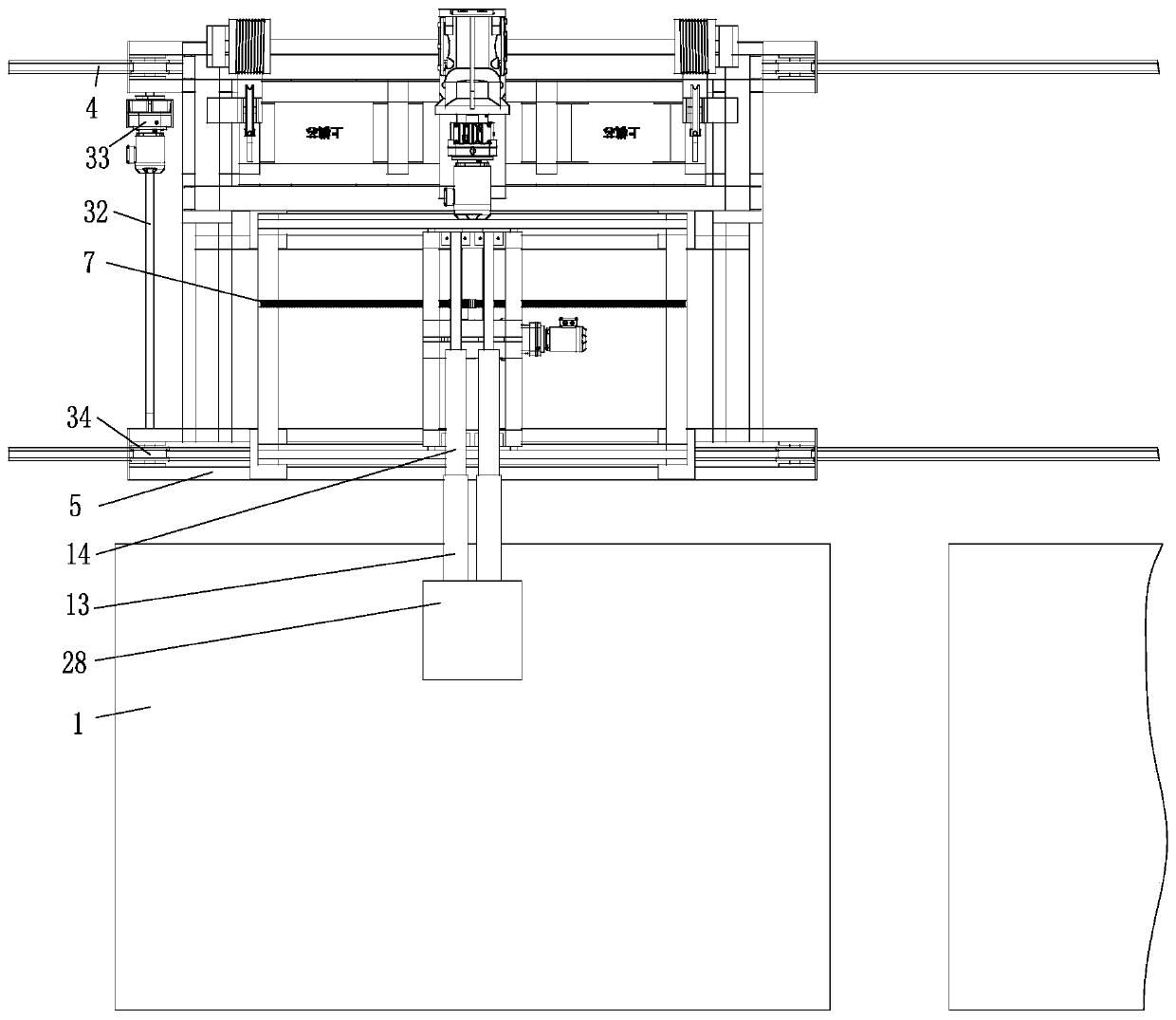
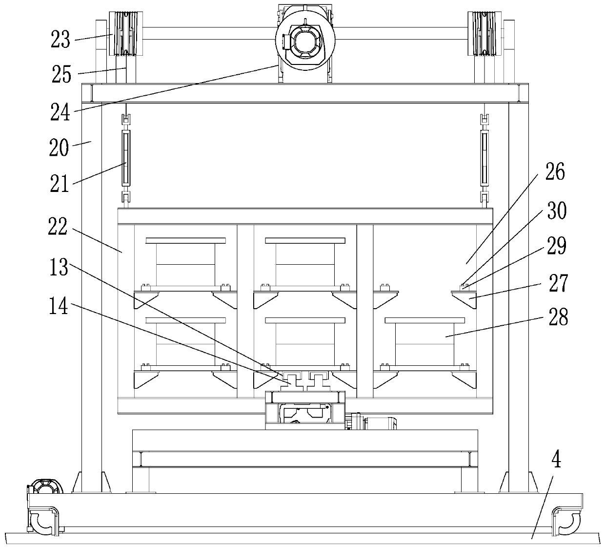
[0022] as attached figure 1 to attach Image 6 Shown: a quick mold change mechanism, including: six workbenches 1 with stamping equipment 3 with a mold lifter 2, a mold change trolley 5 with a walking device and two parallel walking tracks 4, mounted on The mold pick-and-place device on the mold changing trolley 5, the mold storage rack located on the rear side of the mold indexing device and equipped with the mold changing device; the stamping equipment 3 is respectively located on the front side of the mold changing trolley 5 and along the length direction of the walking track 4 set side by side.

[0023]The mold indexing device includes: two shifting rails 6 screwed to the upper end of the mold changing trolley 5 and a shifting rack 7 located between the two shifting rails 6, two one-to-one correspondences are arranged on the two shifting rails. A guide groove 8 ...


PUM


Abstract

The invention relates to a quick die changing mechanism comprising a plurality of stamping apparatuses, a die changing trolley, a die taking and placing device and a die storage frame. Working tablesof the stamping apparatuses are provided with die lifting devices, the die changing trolley is provided with a walking device and a plurality of walking rails arranged in parallel, the die taking andplacing device is installed on the die changing trolley, and the die storage frame is located on the rear side of a die translocation device and provided with a die transposition device; and the stamping apparatuses are located on the front side of the die changing trolley and are arranged side by side in the length direction of the walking rails. The quick die changing mechanism is transposed among the multiple stamping apparatuses through the die changing trolley, dies in the die storage frame and dies mounted on the working tables of the stamping apparatuses are transposed through the die taking and placing device, the die changing time is shortened to be within 5 minutes, time wasted by die changing is short, the labor intensity is small, and the quick die changing mechanism is suitable for meeting the demand for high-efficiency product conversion of an automated production line with the multiple stamping apparatuses.

Description

technical field [0001] The invention relates to the field of stamping die changing, in particular to a quick die changing mechanism and a die changing method. Background technique [0002] The mold replacement on the stamping equipment mainly depends on the mold lifter, mold transfer arm, forklift, driving, etc. on the equipment, which is completed manually; Push it onto the mold transfer arm to remove the equipment, lift the mold away with a crane, forklift or other lifting equipment, then hoist the mold to be replaced onto the mold transfer arm, manually push it to the installation position, and fix it after alignment. The whole process depends on the mold The size takes 30 minutes to 1 hour. In addition, for large molds, there are currently automatic mold change devices used to change molds. The mold pushing device and the guided mold lifting arm will automatically place the mold to the correct installation position and lock it with the mold locker. However, this method ...

Claims


Application Information

Patent Timeline
Patent Type & Authority Applications(China)
IPC IPC(8): B21D37/14
Inventor 许岚计亚平康保和冯峻韩勇
Owner 机械科学研究院浙江分院有限公司
Why Eureka
Try Eureka