Line pressing fixture

A clamp and wire-pressing technology, applied in the field of wire-pressing clamps, can solve the problems of poor use of the clamp, poor clamping of the clamp, and unstable positioning, and achieve a wide range of use, convenient operation and automation, and firm clamping. Effect

Inactive Publication Date: 2019-05-21
江苏英美迪自动化科技有限公司
View PDF0 Cites 0 Cited by
  • Summary
  • Abstract
  • Description
  • Claims
  • Application Information

AI Technical Summary

Problems solved by technology

[0002] Various tools are used when manufacturing many parts, especially when manufacturing electrical cabinets. These parts have different functions. Fixtures are used when manufacturing parts on electrical cabinets. The parts can be clamped well, and the clamping and fixing can be carried out very well, but many clamps are not clamped well, and the positioning is not very stable, resulting in poor use of the clamps

Method used


Image

  • Line pressing fixture

Examples


Embodiment 1

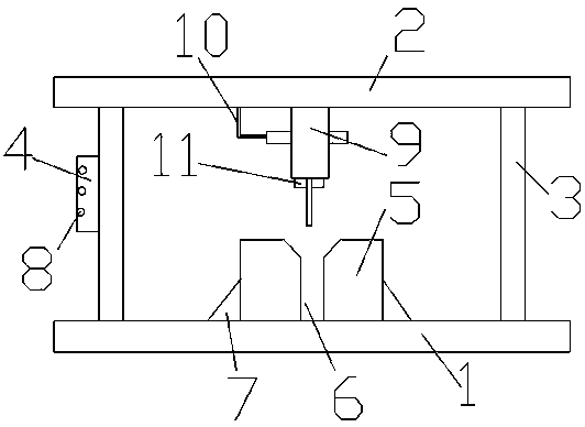
[0013] A wire crimping fixture is provided with a base 1, an operating platform 2 is arranged on the base 1, a connecting rod 3 is arranged between the operating platform 2 and the base 1, and an operating device 4 is arranged on the connecting rod 3. The base 1 is provided with a clamping device 5 , the clamping device 5 and the base 1 are welded and fixed, and the clamping device 5 is provided with a clamping cavity 6 .

[0014] The clamping cavity 6 is an open structure, and the two sides of the clamping device 5 are provided with support plates 7 .

[0015] The support plate 7 is welded and fixed to the side of the clamping device 5, and the support plate 7 is a triangular plate.

[0016] The operating device 4 is a controller, on which a control button 8 is arranged.

[0017] An extruding rod 9 is arranged on the lower side of the operating platform 2, and an extruding head is arranged on the extruding rod 9.

Embodiment 2

[0019] A wire crimping fixture is provided with a base 1, an operating platform 2 is arranged on the base 1, a connecting rod 3 is arranged between the operating platform 2 and the base 1, and an operating device 4 is arranged on the connecting rod 3. The base 1 is provided with a clamping device 5 , the clamping device 5 and the base 1 are welded and fixed, and the clamping device 5 is provided with a clamping cavity 6 .

[0020] The clamping cavity 6 is an open structure, and the two sides of the clamping device 5 are provided with support plates 7 .

[0021] The support plate 7 is welded and fixed to the side of the clamping device 5, and the support plate 7 is a triangular plate.

[0022] The operating device 4 is a controller, on which a control button 8 is arranged.

[0023] An extruding rod 9 is arranged on the lower side of the operating platform 2, and an extruding head is arranged on the extruding rod 9.

[0024] A traction device 10 is arranged on the operation pl...

Embodiment 3

[0026] A wire crimping fixture is provided with a base 1, an operating platform 2 is arranged on the base 1, a connecting rod 3 is arranged between the operating platform 2 and the base 1, and an operating device 4 is arranged on the connecting rod 3. The base 1 is provided with a clamping device 5 , the clamping device 5 and the base 1 are welded and fixed, and the clamping device 5 is provided with a clamping cavity 6 .

[0027] The clamping cavity 6 is an open structure, and the two sides of the clamping device 5 are provided with support plates 7 .

[0028] The support plate 7 is welded and fixed to the side of the clamping device 5, and the support plate 7 is a triangular plate.

[0029] The operating device 4 is a controller, on which a control button 8 is arranged.

[0030] An extruding rod 9 is arranged on the lower side of the operating platform 2, and an extruding head is arranged on the extruding rod 9.

[0031] A traction device 10 is arranged on the operation pl...


PUM


Abstract

The invention provides a line pressing fixture. The line pressing fixture is provided with a base, an operating platform is arranged above the base, connection rods are arranged between the operatingplatform and the base, one of the connection rods is provided with an operating device, the base is provided with a clamping device, the clamping device is welded and fixed with the base, and the clamping device is provided with a clamping cavity. According to the line pressing fixture, the fixture is provided with the clamping device, clamping of components and parts can be made to be more firm,the working effect of the fixture can be made to be better, the clamping requirements for the components and parts of different types are met, the use range of the fixture is made to be wider, and theoperating device can make operations of an extruding rod be more convenient and automated.

Description

technical field [0001] The invention relates to a clamp, in particular to a wire crimping clamp. Background technique [0002] Various tools are used when manufacturing many parts, especially when manufacturing electrical cabinets. These parts have different functions. Fixtures are used when manufacturing parts on electrical cabinets. The parts can be clamped well, and the clamping and fixing can be carried out very well, but many clamps are not clamped well, and the positioning is not very stable, resulting in poor use effect of the clamps. Contents of the invention [0003] The purpose of the present invention is to provide a crimping fixture with reasonable structure and stable positioning. [0004] The technical solution of the present invention is: a wire crimping fixture, which is provided with a base, an operating platform is provided on the base, a connecting rod is provided between the operating platform and the base, and an operating device is provided on the co...

Claims


Application Information

Patent Timeline
Patent Type & Authority Applications(China)
IPC IPC(8): B25B11/00
Inventor 田荣华朱丽丽任引江胡以兵
Owner 江苏英美迪自动化科技有限公司
Why Eureka
Try Eureka