Frame for taking up and paying off cables

A technology of cables and racks, which is applied in the field of racks for receiving and releasing cables, and can solve the problems of fixed cable trays placed on the ground, laborious, and inability to fix cables well

Pending Publication Date: 2019-05-21
WUHU HANGTIAN SPECIAL CABLE FACTORY
View PDF8 Cites 3 Cited by
  • Summary
  • Abstract
  • Description
  • Claims
  • Application Information

AI Technical Summary

Problems solved by technology

[0004] In view of the above technical problems, the purpose of the present invention is to overcome the need to move the cable reel to the working position when manually erecting in the prior art, and then manually pull out the cable and pass it to the operator in the air. When pulling the cable, it cannot be fixed well. The position of the cable makes it very laborious, and the cable reel is fixed on the ground, and the cable stretching direction cannot be adjusted in time according to the change of the working direction.

Method used


Image

  • Frame for taking up and paying off cables
  • Frame for taking up and paying off cables
  • Frame for taking up and paying off cables

Examples


Embodiment Construction

[0032] Specific embodiments of the present invention will be described in detail below in conjunction with the accompanying drawings. It should be understood that the specific embodiments described here are only used to illustrate and explain the present invention, and are not intended to limit the present invention.

[0033] In the present invention, in the absence of a contrary statement, the orientation words included in the term, such as "upper, lower, inner, outer", etc., only represent the orientation of the term in the normal use state, or are understood by those skilled in the art. colloquial term and should not be construed as a limitation of the term.

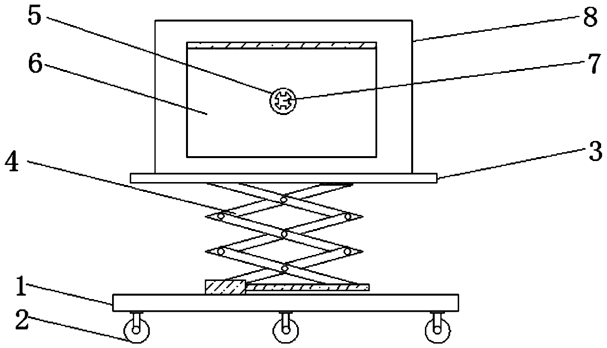
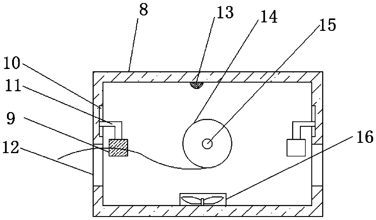
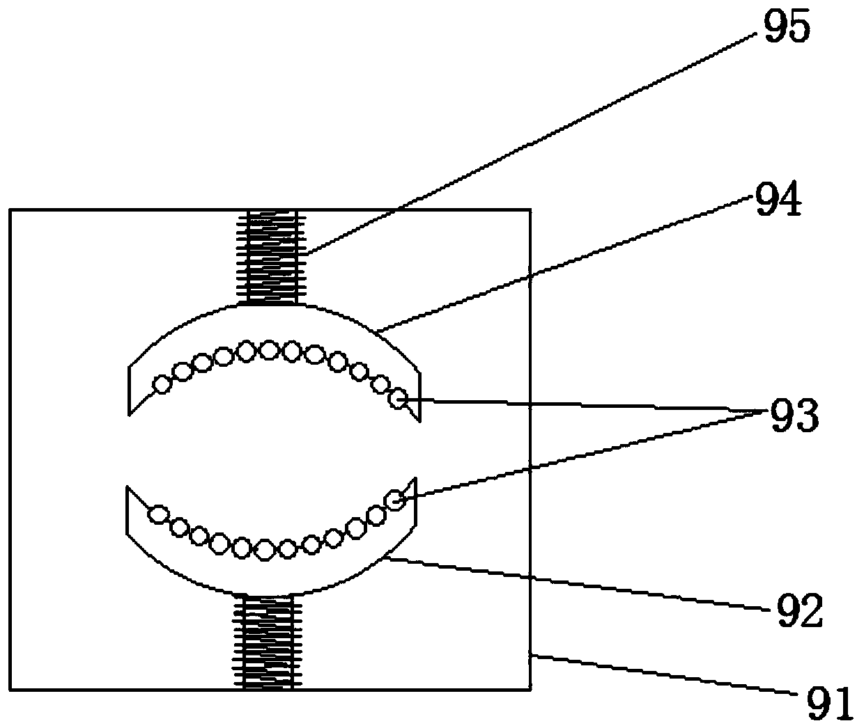
[0034] like Figure 1-3 As shown, the present invention provides a frame for retracting cables. The frame includes: a base 1, a support plate 3, a lifting mechanism 4, a cable box 8 and a self-locking wheel 2; the support plate 3 The lifting mechanism 4 is arranged on the upper surface of the base 1, and the support...


PUM


Abstract

The invention discloses a frame for taking up and paying off cables. The frame comprises a base, a supporting plate, a lifting mechanism, a cable box and self-locking wheels. The supporting plate is arranged on the upper surface of the base through the lifting mechanism, and the supporting plate ascends and descends in the vertical direction. The cable box is fixed to the supporting plate, and themultiple self-locking wheels are arranged on the lower surface of the base at intervals. Wire pay-off openings are formed in the two opposite sides of the cable box correspondingly, a cable is arranged in the cable box through a roll shaft, and cable limiting parts are arranged at the positions, located on the inner sides of the wire pay-off openings, of the cable box. The positions of the cablelimiting parts can be adjusted in the vertical direction. According to the frame, the problems that in the prior art, when the frame is manually erected, a cable reel needs to be moved to the operation position, then the cable is manually pulled out to be transferred to operating personnel in the air, then the cable is pulled and conveyed, the position of the cable cannot be fixed well, and consequently great effort is needed; and the cable reel is fixedly placed on the ground, the cable stretching direction cannot be adjusted in time according to the operation direction are solved.

Description

technical field [0001] The invention relates to the field of cable devices, in particular to a frame for retracting and unwinding cables. Background technique [0002] With the continuous development of social economy, communication equipment occupies a pivotal position in the entire industrial system, and its quality directly affects the quality of industrial products, because many operating requirements are input through the control panel and transmitted to the machine through the communication cable. On the above, if the cable signal is affected, it will directly lead to a decrease in the product qualification rate. At present, when manually erecting, it is necessary to move the cable reel to the working position, and then manually pull out the cable to pass it to the operator in the air. When pulling the cable, it cannot be very fast. It is very laborious to fix the position of the cable well, and the cable reel is fixedly placed on the ground, and the cable stretching d...

Claims


Application Information

Patent Timeline
Patent Type & Authority Applications(China)
IPC IPC(8): B65H75/40B65H75/44
Inventor 章新能何源付利梅许桂红
Owner WUHU HANGTIAN SPECIAL CABLE FACTORY
Why Eureka
Try Eureka