
Electro-hydraulic anchoring device

An anchoring device, electro-hydraulic technology, applied in wellbore/well components, earthwork drilling and production, etc., to achieve stable and reliable anchoring process and large anchoring force

Active Publication Date: 2021-07-27
BC P INC CHINA NAT PETROLEUM CORP +1
View PDF0 Cites 0 Cited by
  • Summary
  • Abstract
  • Description
  • Claims
  • Application Information

AI Technical Summary

Problems solved by technology

It overcomes the deficiency that the existing hydraulic support arms need continuous power from the hydraulic system to work

Method used


Image

  • Electro-hydraulic anchoring device
  • Electro-hydraulic anchoring device
  • Electro-hydraulic anchoring device

Examples


Embodiment Construction

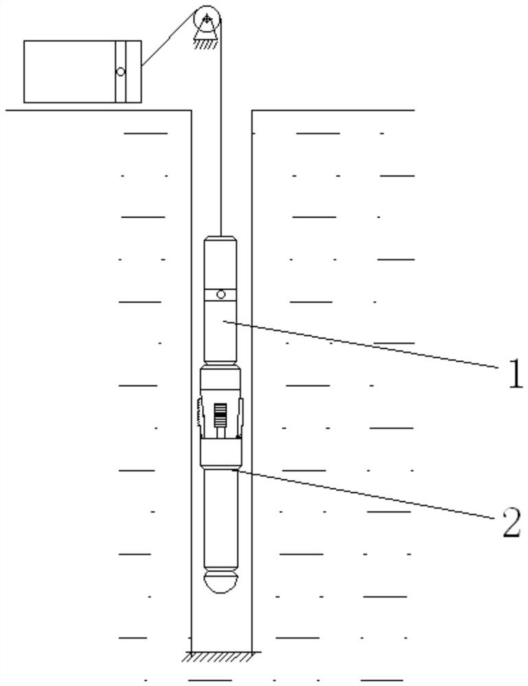
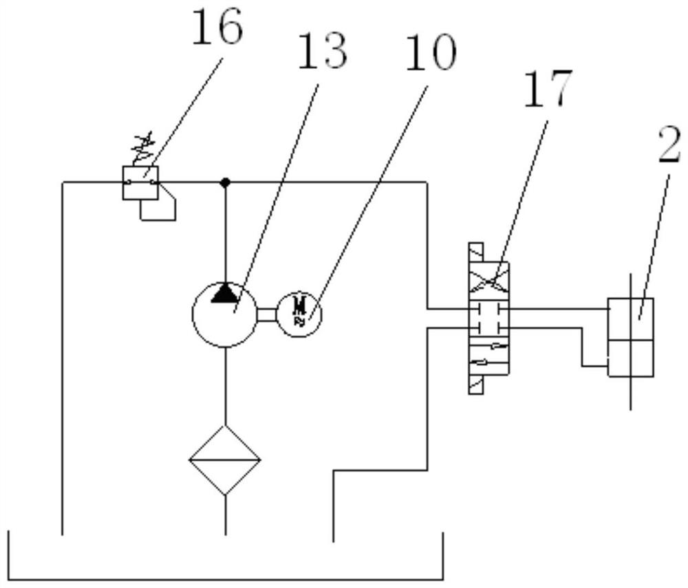
[0021] Such as figure 1 , figure 2 , image 3 , Figure 4 As shown, an electro-hydraulic anchoring device includes a power unit 1 and a mechanical unit 2. The power unit 1 includes a motor 10, a hydraulic pump 13 and an electromagnetic reversing valve 17. The output shaft of the motor 10 is connected to the The input shafts of the hydraulic pump 13 are connected, and different shafts are allowed; the hydraulic pump 13 is connected to the electromagnetic reversing valve 17 through the hydraulic pipe 15, and the overflow valve 16 is installed between the hydraulic pump 13 and the electromagnetic reversing valve 17 The overflow valve 16 is a constant pressure protection element of the hydraulic system, ensuring that the system oil pressure can be stabilized at a set value. The electromagnetic reversing valve 17 has three functions of "X", "II" and "O". The electromagnetic reversing valve 17 can realize three different oil pressure output states.

[0022] The mechanical unit ...


PUM


Abstract

The invention relates to the technical field of well logging and drilling and completion in the petroleum and natural gas industry, in particular to an electro-hydraulic anchoring device. The device includes a power unit and a mechanical unit. The power unit includes a motor, a hydraulic pump and an electromagnetic reversing valve. The output shaft of the motor is connected to the input shaft of the hydraulic pump through a coupling. The hydraulic pump is connected to the electromagnetic reversing valve through a hydraulic pipe. A relief valve is installed between the hydraulic pump and the electromagnetic reversing valve. The invention realizes that the hydraulic system does not need to continuously provide power, the anchoring force is large, and the anchoring process is stable and reliable. After the instrument and the well wall are anchored, the hydraulic system can stop working. Because of the self-locking function, the instrument and the well wall will not be unsealed , to meet the needs of supporting the use of high-power, complex-function downhole instruments.

Description

Technical field: [0001] The invention relates to the technical field of well logging and drilling and completion in the petroleum and natural gas industry, in particular to an electro-hydraulic anchoring device. Background technique: [0002] In the process of oil and gas exploration and development, cables are often used to lower instruments into the well for logging, drilling or sampling operations. However, when the hydraulic support arm is working, the supporting hydraulic system needs to run continuously to keep the instrument and the wellbore fixed. Therefore, during the entire downhole operation, there must be a circuit that continuously supplies power to the hydraulic system to ensure its operation. If the downhole instrument requires multiple motors to work at the same time or requires a large operating current, it is difficult to achieve this requirement due to the limitation of the number of cable cores and the limitation of current transmission capacity. Invent...

Claims


Application Information

Patent Timeline
Patent Type & Authority Patents(China)
IPC IPC(8): E21B23/01E21B23/10
Inventor 刘平全施连海高玮李磊兵张秋阳张帆黄辉建张昕冉董清坤
Owner BC P INC CHINA NAT PETROLEUM CORP
Learn More