
Hydraulic expansion self-locking sealed flushable well packer

A well-flushing packer, closed technology, used in sealing/packing, wellbore/well components, earth-moving drilling, etc. The water injection process has developed to high temperature, high pressure and high efficiency, so as to achieve the effect of reliable sealing and reliable unsealing.

Inactive Publication Date: 2016-08-17
TIANJIN LONGXIN PETROLEUM MACHINERY MFG CO LTD
View PDF3 Cites 0 Cited by
  • Summary
  • Abstract
  • Description
  • Claims
  • Application Information

AI Technical Summary

Problems solved by technology

[0003] However, the traditional K344 packer has prominent defects in the application process. First, the sealing pressure difference of this type of packer is low. When the water injection pressure reaches 12MPa or more, the rubber tube is easily broken down, and the packer loses its seal. , so that the layered water injection string fails; the second is that after the water injection well is stopped, the rubber tube naturally shrinks and unseals. Due to the difference in formation pressure between the water injection layers, the high pressure layer flows to the low pressure layer, which seriously affects the layered water injection effect.
The above defects greatly restrict the application range of the traditional K344 packer, and it is not suitable for the development of high temperature, high pressure and high efficiency in water injection technology.

Method used


Image

  • Hydraulic expansion self-locking sealed flushable well packer
  • Hydraulic expansion self-locking sealed flushable well packer
  • Hydraulic expansion self-locking sealed flushable well packer

Examples


Embodiment Construction

[0026] The present invention will be described in further detail below in conjunction with the accompanying drawings. The following embodiments are only descriptive, not restrictive, and cannot limit the protection scope of the present invention.

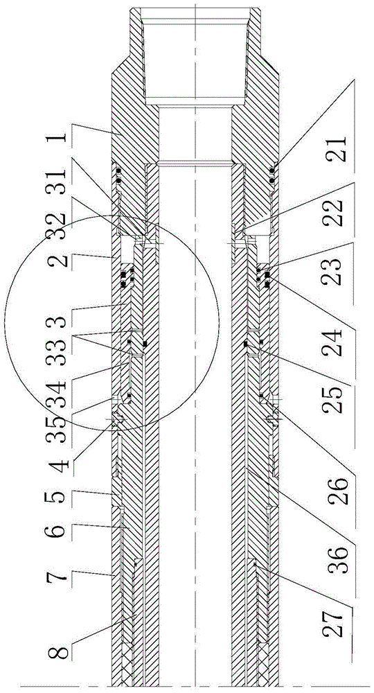
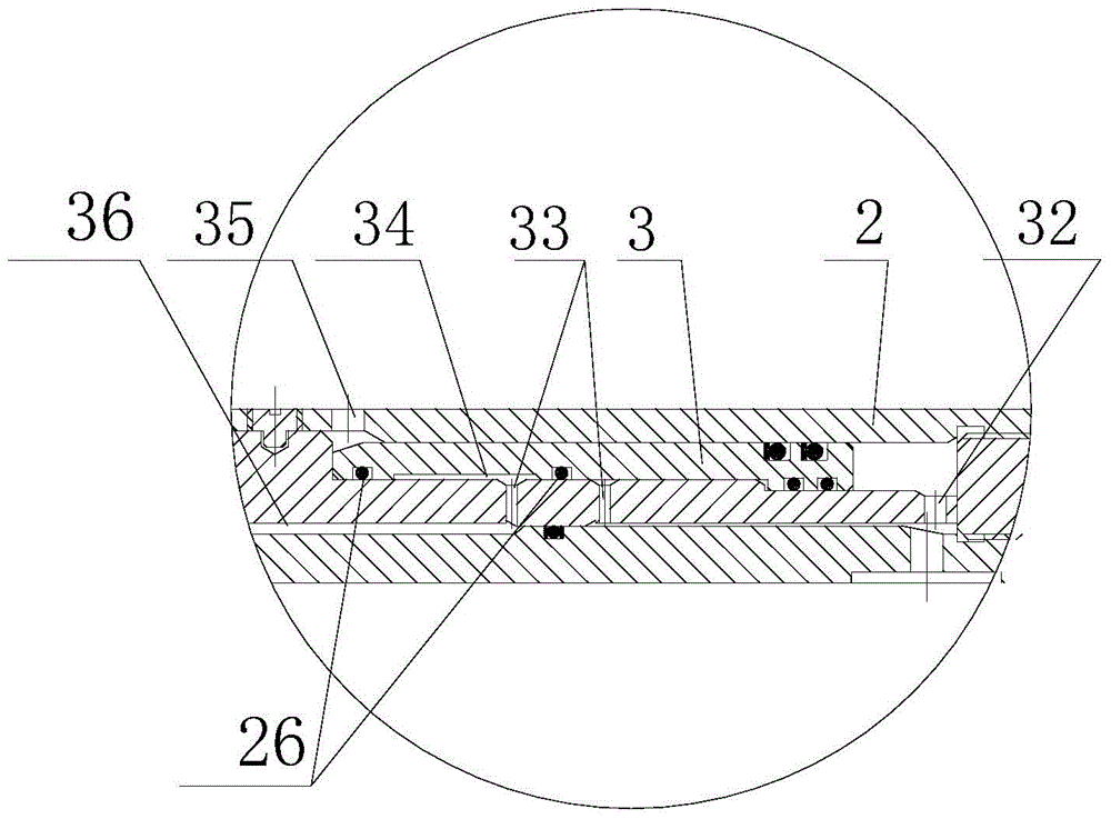
[0027] A hydraulic expansion self-locking hermetic washable well packer, comprising a center pipe 10, a rubber barrel 9, a vulcanized upper joint 8, a vulcanized lower joint 12, an upper joint 1, a lower joint 18, an upper outer short barrel 2, a lower outer Short tube 13, rubber sleeve upper pressure sleeve 7, rubber sleeve lower pressure sleeve 11, the rubber sleeve is set in the middle outside the central tube, the two ends of the rubber sleeve are formed with vulcanized upper joints and vulcanized lower joints, and the two ends of the central tube are fixed by threads. Install the upper joint and the lower joint, install the upper outer short tube and the upper pressure sleeve of the rubber tube between the upper joint and the vu...


PUM


Abstract

The invention relates to a hydraulic expansion self-locking hermetic washable well packer, comprising a center pipe, a rubber barrel, a vulcanized upper joint, a vulcanized lower joint, an upper joint, a lower joint, an upper outer short barrel, a lower outer short barrel, and a rubber barrel upper The pressure sleeve and the lower pressure sleeve of the rubber cylinder are characterized in that: it also includes a self-locking valve mechanism and a conical check valve mechanism. The self-locking valve mechanism is composed of a self-locking valve and an upper sliding sleeve. Between the joint and the upper joint, and between the central tube and the upper outer short tube, the sliding sleeve self-locking valve between the upper part of the upper sliding sleeve and the upper outer short tube; the conical check valve mechanism consists of an inner cone rubber ring and a lower sleeve Composition, the sliding sleeve is axially fixed on the upper part of the lower joint, and radially sleeved between the central tube and the lower outer short tube, the inner cone rubber ring is sleeved between the central tube and the sliding sleeve, and the inner cone rubber ring corresponds to the central tube Made at the lower inlet hole. With a self-locking function, it can ensure the reliability of operations such as layered water injection, layered fracturing, layered acidification, plugging removal, leak detection, channeling detection, channeling closure, and layered testing.

Description

technical field [0001] The invention belongs to a packer of an oil production device, in particular to a hydraulic expansion self-locking hermetic well flushable packer. Background technique [0002] The K344 packer is a hydraulic expansion packer, and it is one of the main tools for layered water injection in oilfields. It is mainly composed of a central tube, an upper joint, a lower joint, a rubber tube, and a floating head, and a liquid inlet hole is formed on the central tube. The principle of the seat seal is: the ground booster pump pumps high-pressure liquid into the annulus of the rubber tube and the center pipe to expand the rubber tube and realize the seat seal. [0003] However, the traditional K344 packer has prominent defects in the application process. First, the sealing pressure difference of this type of packer is low. When the water injection pressure reaches 12MPa or more, the rubber tube is easily broken down, and the packer loses its seal. , so that the...

Claims


Application Information

Patent Timeline
Patent Type & Authority Patents(China)
IPC IPC(8): E21B33/126
Inventor 张兵曹帮元
Owner TIANJIN LONGXIN PETROLEUM MACHINERY MFG CO LTD
Learn More