
Detection fixture with power supply protection device

A technology for detecting fixtures and power supply protection, applied in the direction of overload protection devices, etc., can solve problems such as electric shock and cannot effectively reduce electric shock, and achieve the effect of reducing the risk of electric shock

Active Publication Date: 2021-04-30
PEGATRON
View PDF7 Cites 0 Cited by
  • Summary
  • Abstract
  • Description
  • Claims
  • Application Information

AI Technical Summary

Problems solved by technology

[0005] However, the power supply continues to supply power to the thimble after the test is over, so the operator may accidentally touch the thimble or the product under test when the operator lifts the pressure plate, and there is a risk of electric shock; especially the thimble may carry high voltage (possibly up to 220V), so the risk of electric shock should not be underestimated
Therefore, the thimble fixture of the prior art cannot effectively reduce the possibility of electric shock, so it really needs to be improved.

Method used


Image

  • Detection fixture with power supply protection device
  • Detection fixture with power supply protection device

Examples


Embodiment Construction

[0018] In the following, the technical means adopted by the present invention to achieve the intended purpose of the invention will be further described in conjunction with the accompanying drawings and preferred embodiments of the present invention.

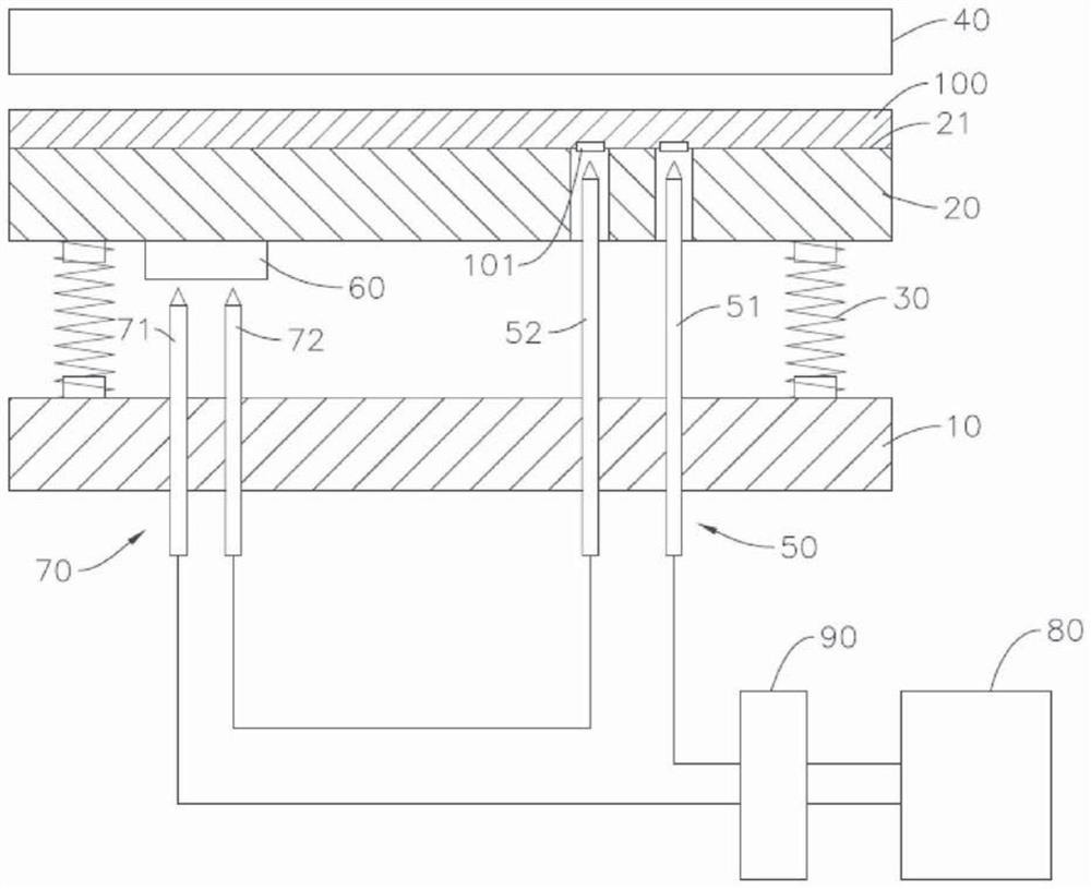
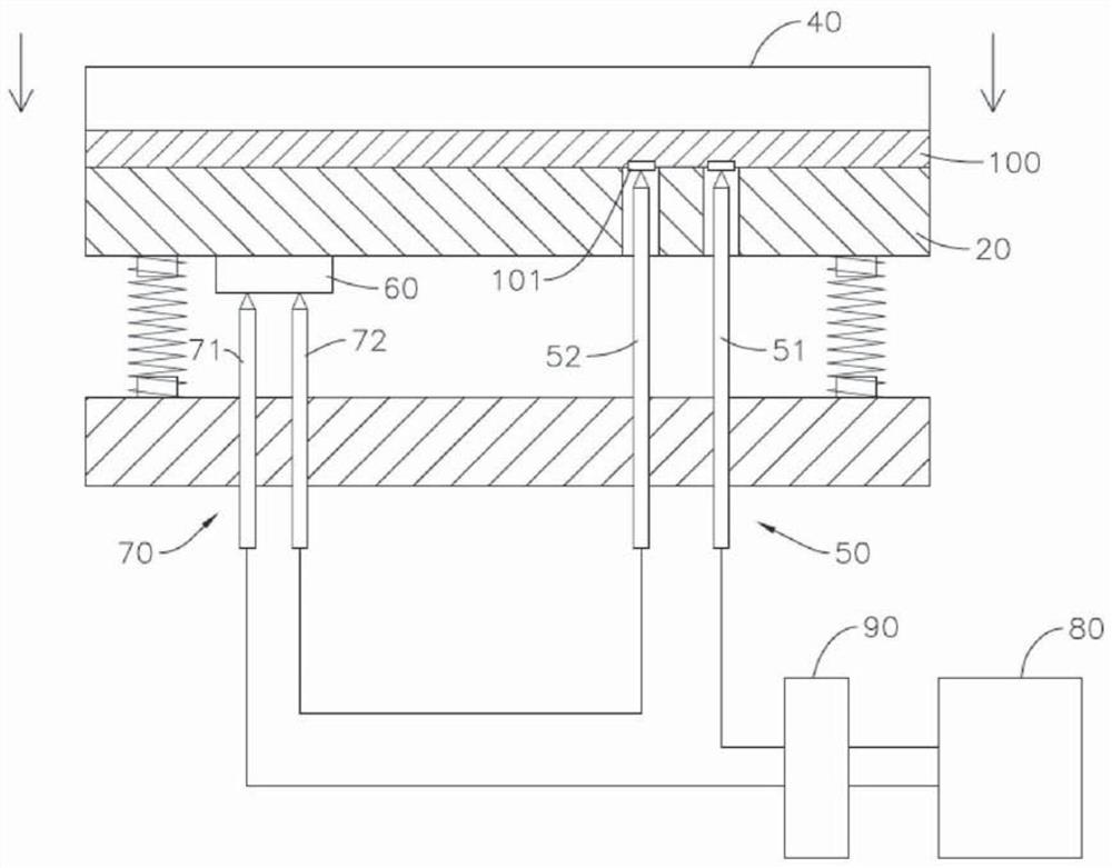
[0019] see figure 1 As shown, the detection jig with power supply protection device of the present invention includes a bottom plate 10, a carrier plate 20, at least one elastic element 30, a pressure plate 40, a first thimble group 50, a conductive sheet 60, a second thimble Group 70, a power supply 80 and a hand-cut switch 90; the press-fit detection fixture of the present invention is used to detect a product to be tested 100, and the product to be tested 100 has two power supply points 101. In this embodiment, the product to be tested 100 is a circuit board, but not limited thereto.

[0020] The aforementioned carrier board 20 is spaced above the base plate 10 , and the top surface 21 of the carrier board 20 is used to carr...


PUM


Abstract

The present invention is a detection jig with a power supply protection device, which includes a carrier board, at least one elastic element, a first thimble group, a conductive sheet, a second thimble group and a power supply; When the carrier board moves down to the power supply point of the product to be tested on the carrier board and touches the first thimble group, the distance that the carrier board drops is just to make the conductive sheet on the carrier board contact the second thimble group downwards, so The power supply, the first thimble group, the product to be tested, the second thimble group and the conductive sheet form a loop to allow the power supply to supply power to the product to be tested; when the pressure plate is lifted up, the elastic element pushes up against the carrier plate so that the conductive sheet and the second thimble The groups are separated to form an open circuit in the circuit; thus, in the process of lifting the pressure plate, even if the first thimble group or the product under test are touched by mistake, there will be no electric shock.

Description

technical field [0001] The invention relates to a thimble jig for conducting electrical tests on electronic products such as circuit boards, in particular to a testing jig with a power supply protection device. Background technique [0002] In the prior art, electronic products to be tested (such as circuit boards) are often tested through a thimble jig, and the thimble jig usually includes devices such as a carrier board, a spring, a pressure plate, a thimble, and a power supply. [0003] When using the aforementioned jig, first place the electronic product to be tested on the top surface of the carrier board, and align the power supply point on the bottom of the product to be tested with the thimble; then push the product to be tested and the carrier board down through the pressure plate until the bottom of the product to be tested The power supply point of the thimble contacts the top of the thimble, and the power supply supplies power to the product under test through th...

Claims


Application Information

Patent Timeline
Patent Type & Authority Patents(China)
IPC IPC(8): G01R1/36
Inventor 廖婕宇
Owner PEGATRON
Learn More