Projection interaction method, device and system and terminal equipment
A technology of projection interaction and projection surface, which is applied in the field of data processing, can solve the problems of difficult portability and high projection cost, and achieve the effect of reducing projection cost and improving convenience
- Summary
- Abstract
- Description
- Claims
- Application Information
AI Technical Summary
Problems solved by technology
Method used
Image

Examples
Embodiment 1
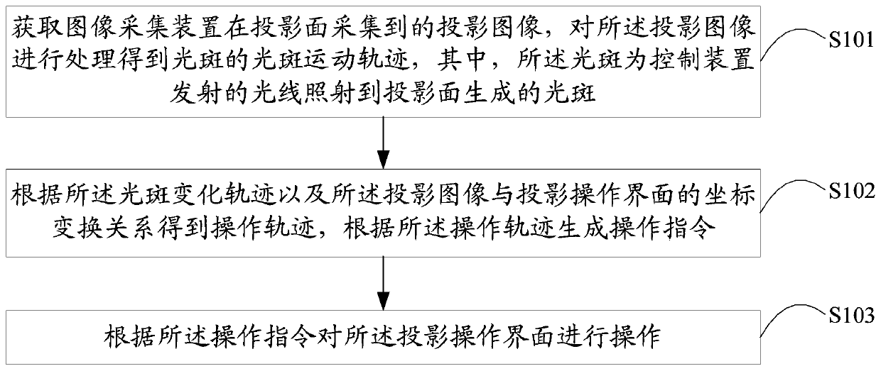
[0039] A projection interaction method provided by Embodiment 1 of the present application is described below, please refer to the attached figure 1 , the projection interaction method in Embodiment 1 of the present application includes:
[0040] Step S101: Obtain the projection image collected by the image acquisition device on the projection surface, and process the projection image to obtain the change trajectory of the light spot, wherein the light spot is the light spot generated by the light emitted by the control device irradiating the projection surface;
[0041] In the projection interaction method of this embodiment, the projector projects the image of the projection operation interface onto the projection surface, and when the user needs to perform projection interaction, the control device can operate the projection image on the projection surface.
[0042] The control device can emit light, and the user can operate the control device, and the emitted light irradia...
Embodiment 2
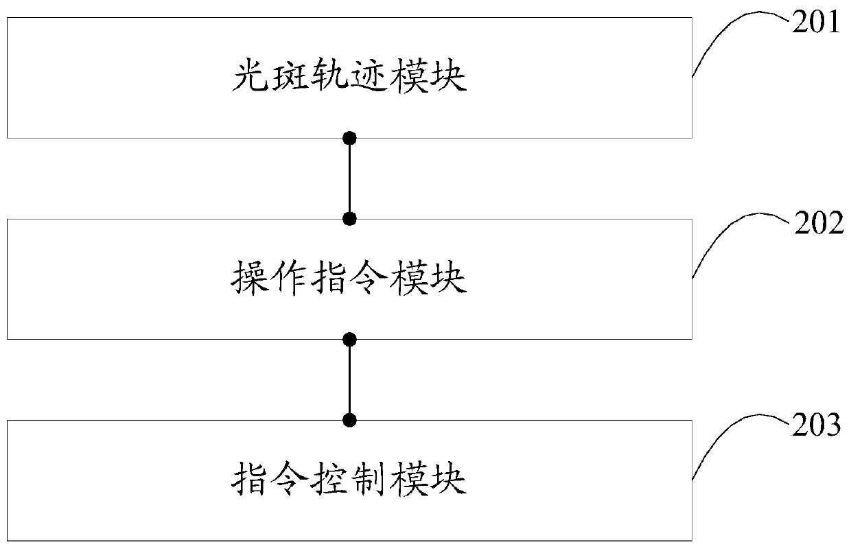
[0077] Embodiment 2 of the present application provides a projection interaction device. For the convenience of description, only the parts related to the present application are shown, such as figure 2 As shown, the projection interaction device includes,
[0078] The spot trajectory module 201 is configured to acquire the projection image collected by the image acquisition device on the projection surface, and process the projection image to obtain the spot change trajectory of the spot, wherein the spot is generated by the light emitted by the control device irradiating the projection surface the spot;
[0079] An operation instruction module 202, configured to obtain an operation trajectory according to the light spot change trajectory and the coordinate transformation relationship between the projection image and the projection operation interface, and generate an operation instruction according to the operation trajectory;
[0080] The instruction control module 203 is...
Embodiment 3
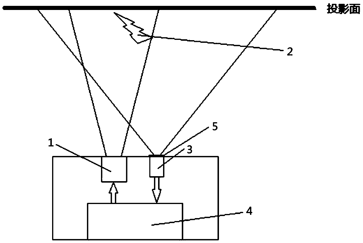
[0089] Embodiment 3 of the present application provides a projection interaction system. For the convenience of description, only the parts related to the present application are shown, such as image 3 As shown, the projection interaction system includes: a projector 1, a control device 2, an image acquisition device 3, and any projection interaction device 4 mentioned above;
[0090] The projector 1 and the image acquisition device 3 are respectively connected in communication with the projection interaction device 4;
[0091] The control device 2 is used for emitting light to the projection surface.
[0092] The viewing angle of the camera in the image acquisition device 3 should be larger than the projection angle of the projector 1, so that the camera can capture a complete projected image. The camera can be a high-definition camera, the acquisition frame rate can be selected to be greater than 24 frames per second, and the exposure can be adjusted according to actual ne...
PUM
 Abstract
Description
Claims
Application Information
 - R&D Engineer
- R&D Manager
- IP Professional
- Industry Leading Data Capabilities
- Powerful AI technology
- Patent DNA Extraction
Browse by: Latest US Patents, China's latest patents, Technical Efficacy Thesaurus, Application Domain, Technology Topic.
© 2024 PatSnap. All rights reserved.Legal|Privacy policy|Modern Slavery Act Transparency Statement|Sitemap