Tunnel construction lighting device good in protecting effect

A technology for tunnel construction and protection effect, which is applied to lighting devices, fixed lighting devices, components of lighting devices, etc., can solve problems such as unsatisfactory protection effects, and achieve the purpose of increasing the lighting range, preventing damage and avoiding potential safety hazards. Effect

Active Publication Date: 2019-05-24
东营宏基混凝土有限公司
View PDF6 Cites 7 Cited by
  • Summary
  • Abstract
  • Description
  • Claims
  • Application Information

AI Technical Summary

Problems solved by technology

[0003] The purpose of the present invention is to provide a lighting device for tunnel construction with good protection effect, which has the advantage of good protection effect and solves the problem of unsatisfactory protection effect of common lighting devices for tunnel construction

Method used


Image

  • Tunnel construction lighting device good in protecting effect
  • Tunnel construction lighting device good in protecting effect

Examples


no. 1 approach

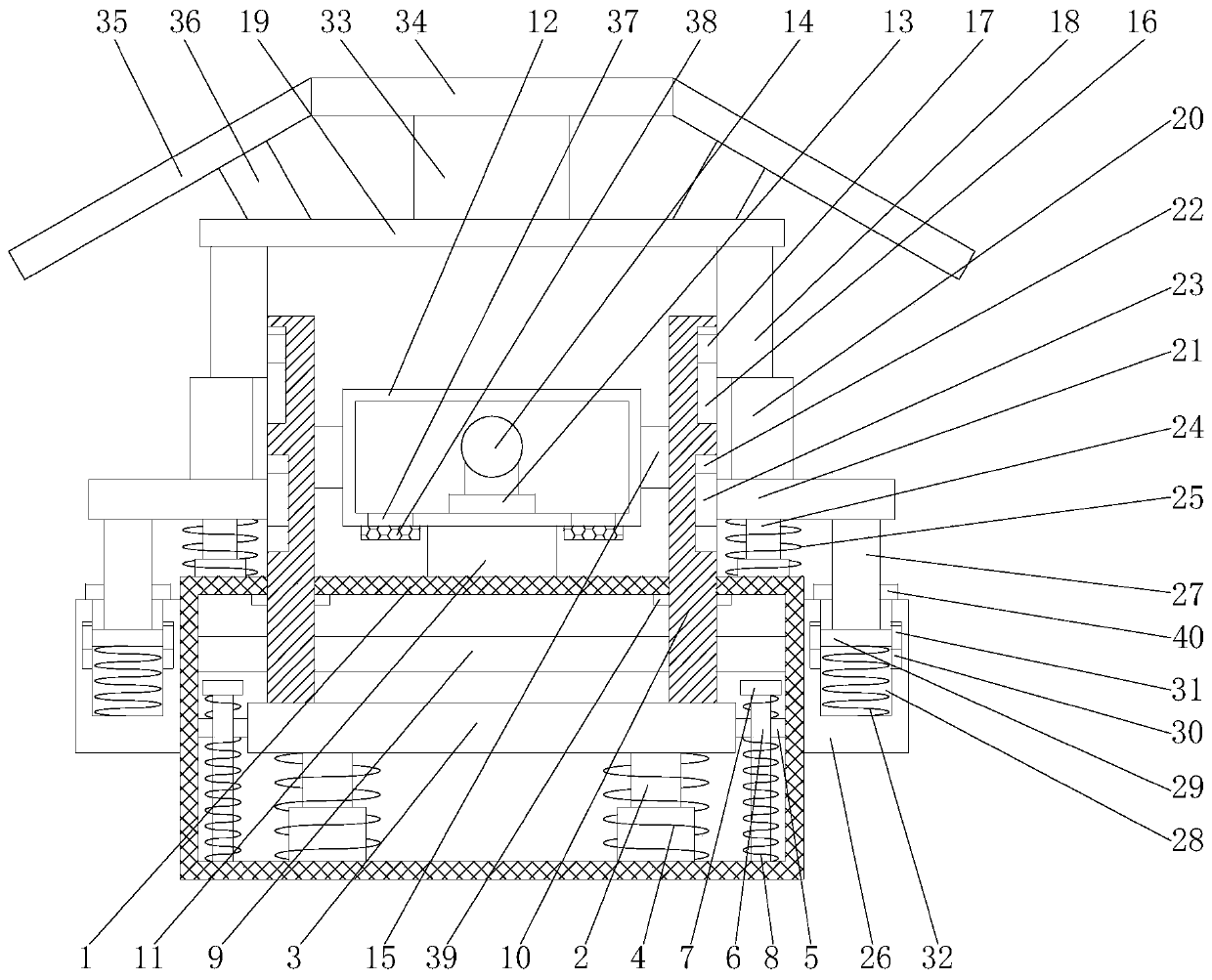
[0016] First implementation: see Figure 1-2, a lighting device for tunnel construction with good protection effect, comprising a box body 1, two first telescopic rods 2 are fixedly connected to the bottom of the inner wall of the box body 1, and the tops of the two first telescopic rods 2 are fixedly connected through a sliding plate 3 , the surface of the first telescopic rod 2 is sleeved with a first spring 4, the top and bottom of the first spring 4 are fixedly connected with the top of the sliding plate 3 and the bottom of the inner wall of the box body 1 respectively, and the left and right sides of the sliding plate 3 are The sliding block 5 is fixedly connected, the top of the sliding block 5 is provided with a sliding rod 6, the bottom end of the sliding rod 6 runs through the sliding block 5 and extends to the outside and is fixedly connected with the bottom of the inner wall of the box body 1, and the top of the sliding rod 6 is fixedly connected The limit block 7, ...

no. 2 approach

[0019] The second embodiment: a lighting device for tunnel construction with good protection effect, including a box body 1, two first telescopic rods 2 are fixedly connected to the bottom of the inner wall of the box body 1, and the tops of the two first telescopic rods 2 Through the fixed connection of the sliding plate 3, the surface of the first telescopic rod 2 is sleeved with a first spring 4, and the top and bottom ends of the first spring 4 are respectively fixed to the top of the sliding plate 3 and the bottom of the inner wall of the box body 1. connected, the left and right sides of the sliding plate 3 are fixedly connected with sliding blocks 5, the top of the sliding block 5 is provided with a sliding bar 6, the bottom end of the sliding bar 6 runs through the sliding block 5 and extends to its outside and The bottom of the inner wall of the box body 1 is fixedly connected, the top of the sliding rod 6 is fixedly connected to the limit block 7, the surface of the s...


PUM


Abstract

The invention discloses a tunnel construction lighting device good in protecting effect. The tunnel construction lighting device comprises a box and is characterized in that two first telescopic rodsare fixedly connected to the bottom of the inner wall of the box, and the tops of the two first telescopic rods are fixedly connected through a slide plate. The tunnel construction lighting device hasthe advantages that by the coordination of the first telescopic rods, the slide plate, first springs, sliders, slide rods, limit blocks, second springs, a fixing plate, dustproof plates, first slidegrooves, first sliders, second slide grooves, second sliders, second telescopic rods, reset springs, fixing seats, support rods, fixing grooves, squeezing blocks, third slide grooves, third sliders and third springs, the problem that a common tunnel construction lighting device is unsatisfactory in protecting effect is solved, a gravel damping effect is achieved during tunnel construction, the lighting device is prevented from being smashed, the service life of the lighting device is prolonged, potential safety hazards are avoided, and great convenience is brought to tunnel construction.

Description

technical field [0001] The invention relates to the technical field of tunnels, in particular to a lighting device for tunnel construction with good protection effect. Background technique [0002] A tunnel is a building built underground or underwater or in a mountain, laying a railway or building a road for the passage of motor vehicles. According to its location, it can be divided into three categories: mountain tunnels, underwater tunnels and urban tunnels. In order to shorten the distance and avoid large ramps, it is called a mountain tunnel that passes under mountains or hills. In order to cross rivers or straits, it is called an underwater tunnel that passes under a river or under the sea. Those that pass underground are called urban tunnels. Among the three types of tunnels, mountain tunnels are the most built. The light in the tunnel is dim, and the construction workers need lighting devices to carry out tunnel construction. The protection effect of common lightin...

Claims


Application Information

Patent Timeline
Patent Type & Authority Applications(China)
IPC IPC(8): F21S8/00F21V15/04F21V15/01F21V13/04F21V29/83F21V31/00F21W131/101
Inventor 李友新
Owner 东营宏基混凝土有限公司
Why Eureka
Try Eureka