Internal circulation type lubricating self-cleaning mechanism

A self-cleaning, internal circulation technology, applied in the direction of manipulators, joints, manufacturing tools, etc., can solve the problem of robot penetration of grease and other problems, achieve the effects of small rotation resistance, increased heat dissipation area, and stable internal pressure

Active Publication Date: 2019-05-28
SHENYANG SIASUN ROBOT & AUTOMATION
View PDF7 Cites 2 Cited by
  • Summary
  • Abstract
  • Description
  • Claims
  • Application Information

AI Technical Summary

Problems solved by technology

[0004] In order to solve the problem of grease penetration by robots in the cleaning industry, the purpose of the present invention is to provide an internal circulation lubricating self-cleaning mechanism

Method used


Image

  • Internal circulation type lubricating self-cleaning mechanism
  • Internal circulation type lubricating self-cleaning mechanism

Examples


Embodiment Construction

[0018] The present invention will be described in further detail below in conjunction with the accompanying drawings.

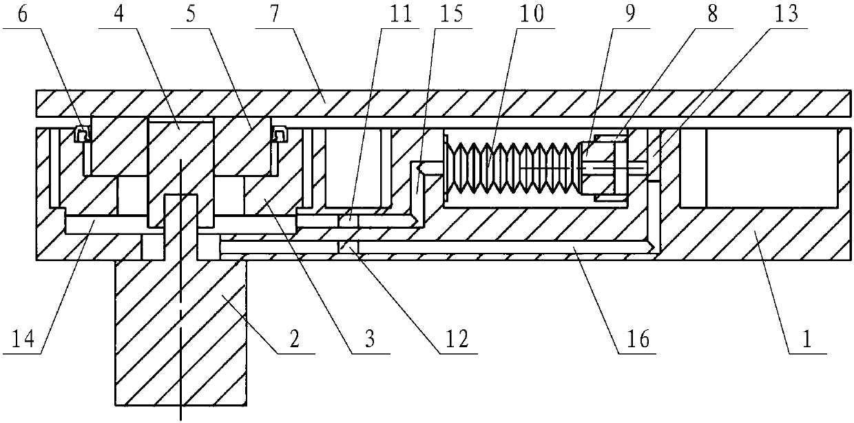
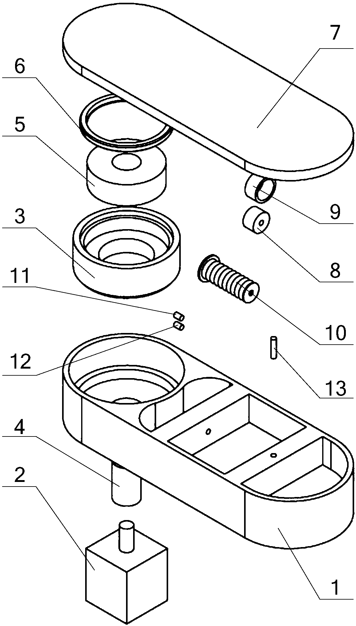
[0019] Such as figure 1 , figure 2 As shown, the present invention includes a boom 1, a small arm 7, a motor 2 and a reducer housing 3 respectively accommodated in the boom 1, a reducer input gear shaft 4, a reducer output shaft 5, an elastic mechanism 10, an oil outlet One-way valve 11, oil return one-way valve 12 and filter element 13, in which the motor 2 is statically sealed and fixedly connected to the boom 1, the output end penetrates into the boom 1, through the input gear shaft 4 of the reducer and the output shaft 5 of the reducer One end of the reducer casing 3 is statically sealed and fixedly connected to the boom 1, and the other end is connected to the output shaft 5 of the reducer through a rotating dynamic seal 6. The other end of the reducer casing 3 is connected to the input shaft of the reducer. The gear shaft 4, the output shaft 5 of the...


PUM


Abstract

The invention relates to an internal circulation type lubricating self-cleaning mechanism. A motor is connected to a large arm in a static sealing manner, the output end is connected with one end of an output shaft of a speed reducer through an input gear shaft of the speed reducer, one end of a shell of the speed reducer is fixedly arranged in the large arm in a static sealing mode, the other endof the shell of the speed reducer is in sealing rotation connection with the output shaft of the speed reducer, and the other end of the output shaft of the speed reducer is in static sealing connection with a small arm; an inner cavity of the speed reducer is arranged in the large arm, the inner cavity of the speed reducer is in communication with one end of an elastic mechanism through an oil way A, the other end of the elastic mechanism is in communication with the inner cavity of the speed reducer through an oil way B, an oil outlet one-way valve which can only flow to the elastic mechanism is arranged in the oil way A, and an oil return one-way valve which can only flow to the inner cavity of the speed reducer is arranged in the oil way B; and close to the other end of the elastic mechanism, of the oil way B is provided with a filter element. According to the internal circulation type lubricating self-cleaning mechanism, the internal pressure of a robot joint can be stabilized, oil seepage is prevented, the joint rotation resistance of the robot is small, the energy efficiency is reduced, and the energy-saving and environment-friendly effects are better and remarkable.

Description

technical field [0001] The invention relates to a cleaning lubricating system for robot joints in the cleaning industry, in particular to an internal circulation lubricating self-cleaning mechanism. Background technique [0002] The joints of the robot contain motors and reducers. For routine applications, there may be oil leakage or leakage for many reasons. However, it is absolutely not allowed to be used in the clean industry. If the reducer is in a relatively closed state, a certain amount of friction will be generated between each pair of gears in the reducer, and this friction will emit a certain amount of heat; The extension of time will directly lead to a certain degree of temperature increase in the reducer box; and the volume of the reducer box remains unchanged, so the pressure in the reducer box will also increase accordingly, and the lubricating oil in the box will After splashing, it will be sprinkled on the inner wall of the gear box. Since the oil is relat...

Claims


Application Information

Patent Timeline
Patent Type & Authority Applications(China)
IPC IPC(8): B25J19/00B25J17/00
Inventor 朱维金陈立博孙宝龙刘亚超王凤利王世超王金涛曲业闯
Owner SHENYANG SIASUN ROBOT & AUTOMATION
Why Eureka
Try Eureka