
Locking device and lottery self-service vending machine

A locking device and locking technology, applied in lottery equipment, building locks, non-mechanical transmission-operated locks, etc., can solve the problems of inconvenient operation and poor anti-theft performance of cabinet door locks, and achieve the improvement of anti-theft performance, simplification, Improved anti-theft effect

Pending Publication Date: 2019-05-31
HEFEI HUIKE JINYANG TECH
View PDF3 Cites 1 Cited by
  • Summary
  • Abstract
  • Description
  • Claims
  • Application Information

AI Technical Summary

Problems solved by technology

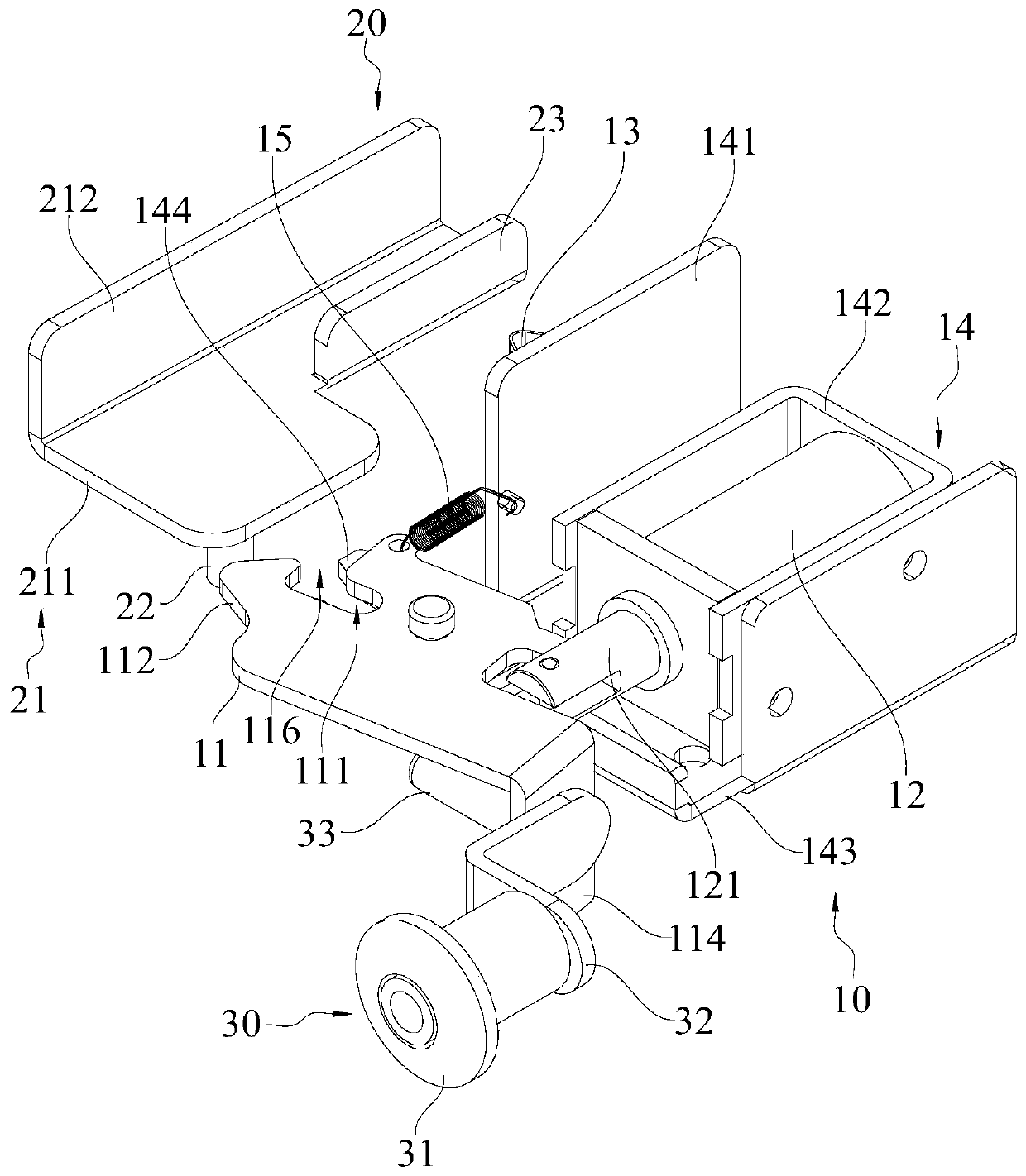
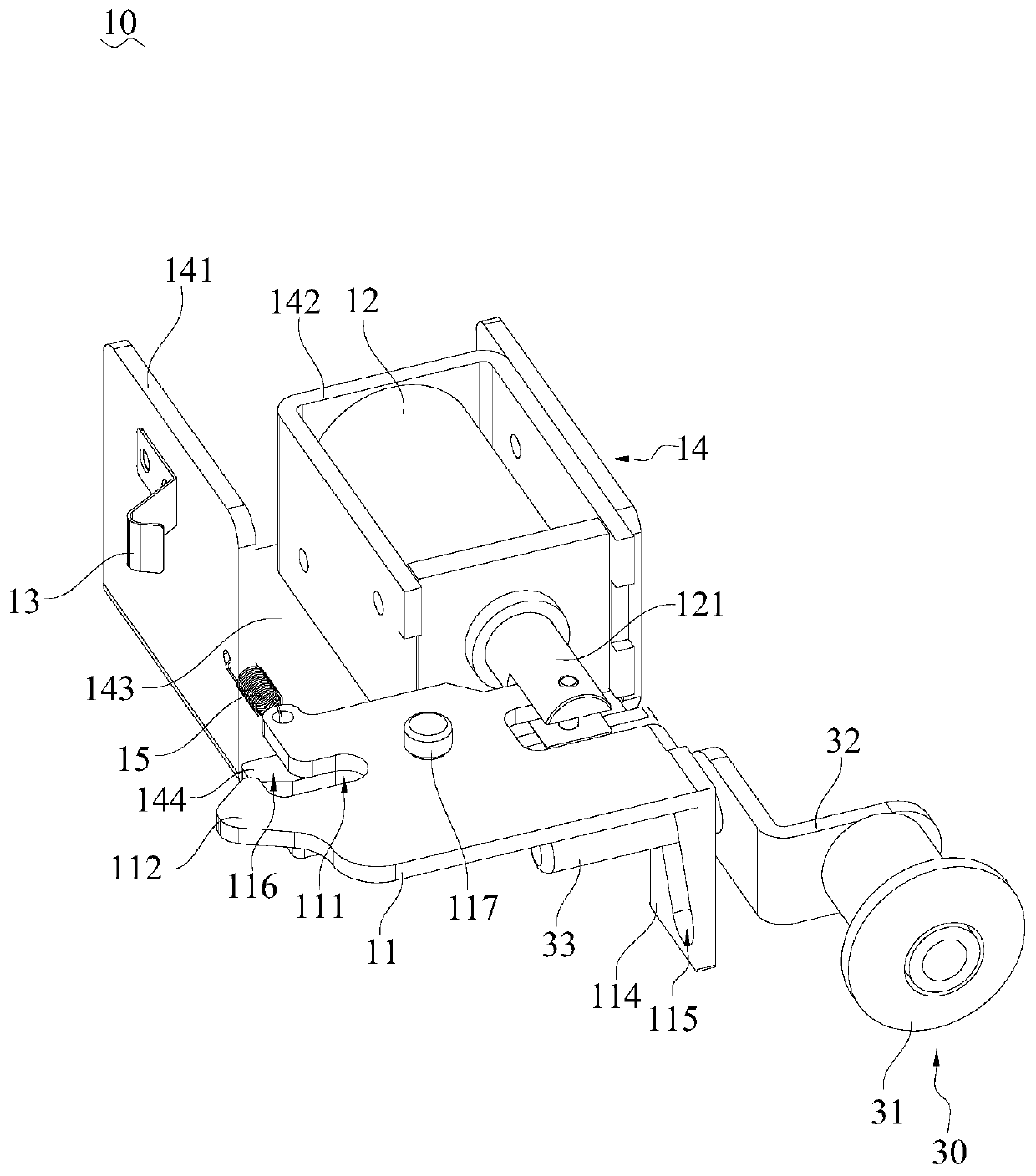
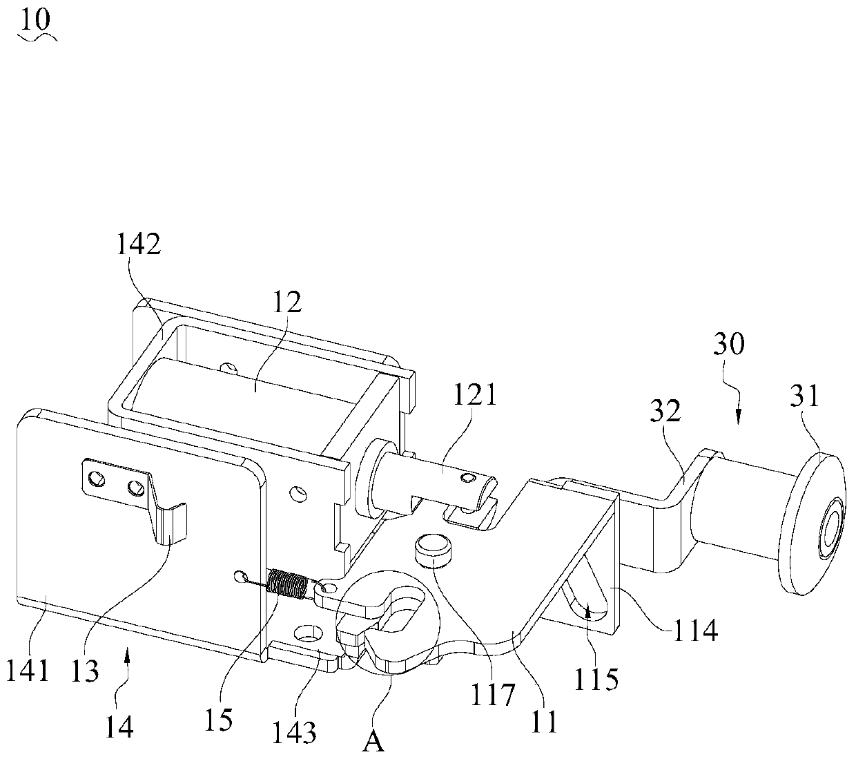
[0004] The purpose of this application is to provide a locking device and a lottery self-service vending machine, which aims to solve the technical problems of inconvenient operation and poor anti-theft performance of the cabinet door lock of the lottery self-service vending machine

Method used


Image

  • Locking device and lottery self-service vending machine
  • Locking device and lottery self-service vending machine
  • Locking device and lottery self-service vending machine

Examples


Embodiment Construction

[0037] In order to make the purpose, technical solutions and advantages of this application clearer, the following in conjunction with the attached Figure 1~5 And embodiment, this application is described in further detail. It should be understood that the specific embodiments described here are only used to explain the present application, not to limit the present application.

[0038] It should be noted that when a component is referred to as being “fixed on” or “disposed on” another component, it may be directly or indirectly located on the other component. When an element is referred to as being "connected to" another element, it can be directly or indirectly connected to the other element. The terms "upper", "lower", "left", "right", "front", "rear", "vertical", "horizontal", "top", "bottom", "inner", "outer", etc. The indicated orientation or position is based on the orientation or position shown in the drawings, and is only for convenience of description, and should ...


PUM


Abstract

The invention belongs to the technical field of equipment door locks, and provides a locking device and a lottery self-service vending machine. The locking device comprises a lock body mechanism and alock plate mechanism, the lock body mechanism comprises a spring bolt, a relay, a touch spring piece and a mounting frame body, the spring bolt is connected with the mounting frame body and can rotate, the relay is rotationally connected with the spring bolt so as to drive the spring bolt to rotate to an unlocking position to be kept in a locking position, and the touch spring piece is mounted onthe mounting frame body and used for controlling the relay to be powered on or off. The lock plate mechanism comprises a lock plate, a locking pin post and a contact chip, the locking pin post is used for being locked fit with or separated from the spring bolt, the relay is used for driving the spring bolt to be in the locking position when powered on and driving the spring bolt to the unlockingposition when powered off, and the contact chip is used for triggering the touch spring piece. The locking device can be opened and closed only by controlling the relay to be powered on or off, operation is remarkably simplified and made convenient, the locking device can be mounted in a concealed mode in an external cabinet body and a cabinet door when installed, and anti-theft performance is improved.

Description

technical field [0001] The application belongs to the technical field of equipment door locks, in particular to a locking device and a lottery self-service vending machine. Background technique [0002] In recent years, with the advancement of technology, lottery self-service vending machines have begun to appear in consumer places such as hotel lobbies, large supermarkets, and shopping malls, which greatly facilitates the lottery ticket purchase needs of lottery players. The lottery self-service vending machine is usually provided with a cabinet door and a door lock for locking the cabinet door. [0003] In the prior art, the door lock of the lottery self-service vending machine is usually a mechanical linkage lock. Although the effective locking of the lottery self-service vending cabinet door can be realized in this way, it is limited by the inherent structure of the mechanical linkage lock. The lock still has the problems of inconvenient opening and closing operation an...

Claims


Application Information

Patent Timeline
Patent Type & Authority Applications(China)
IPC IPC(8): E05B65/52E05B47/00E05B15/00E05B15/10G07C15/00
Inventor 王智勇刘辅荣
Owner HEFEI HUIKE JINYANG TECH
Learn More