Field air detecting device based on steady erection technology

A technology of air detection and technology, applied in the direction of measuring devices, mechanical equipment, machines/supports, etc., can solve the problems of large cost, high ground requirements, inconvenience, etc., and achieve the effect of increasing stability, reducing requirements, and convenient application

Inactive Publication Date: 2019-05-31
胡昌兵
View PDF7 Cites 3 Cited by
  • Summary
  • Abstract
  • Description
  • Claims
  • Application Information

AI Technical Summary

Problems solved by technology

[0004] In order to monitor and understand the air quality in the field, it is necessary for the staff to set up air detection devices in the field to detect the air. This kind of detection activity has a high work intensity, especially when setting up air detection equipment on different terrains, it is very hard work, and The existing air equipment has high requirements on the ground, and the staff need to spend a lot of time looking for a suitable terrain to set up the air detection equipment, which is very inconvenient

Method used


Image

  • Field air detecting device based on steady erection technology
  • Field air detecting device based on steady erection technology
  • Field air detecting device based on steady erection technology

Examples


Embodiment 1

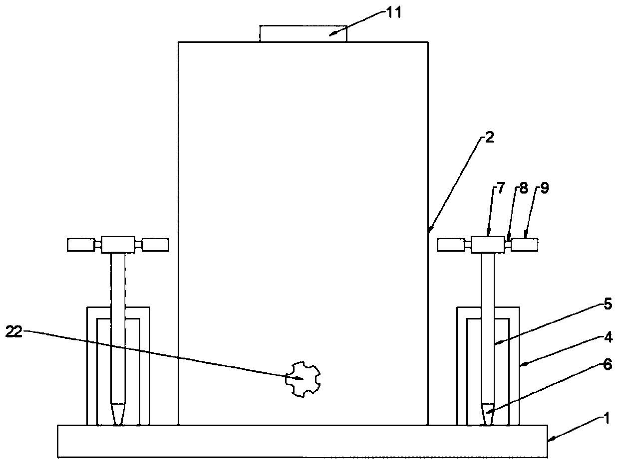
[0026] see Figure 1~3 , a field air detection device based on stable erection technology, comprising a base 1, a plurality of through holes 3 are uniformly arranged on the edge of the base 1, a detection box 2 is arranged in the center of the top of the base 1, and the top edge of the base 1 is evenly There are several stabilizing frames 4 matched with the through holes 3, the stabilizing frame 4 is a U-shaped structure, and the top wall of the stabilizing frame 4 is embedded with a screw rod 5 matched with the through hole 3, and the screw rod 5 is connected with the stabilizing frame 4 are threaded connections, and there is a one-to-one relationship between the screw rod 5 and the through hole 3. The bottom end of the screw rod 5 is fixedly connected with the anchor thorn 6, and the bottom end of the screw rod 5 is fixedly connected with the turntable 7. The axis of the screw rod 5 is connected with the The axes of the turntable 7 coincide, and by turning the turntable 7, t...

Embodiment 2

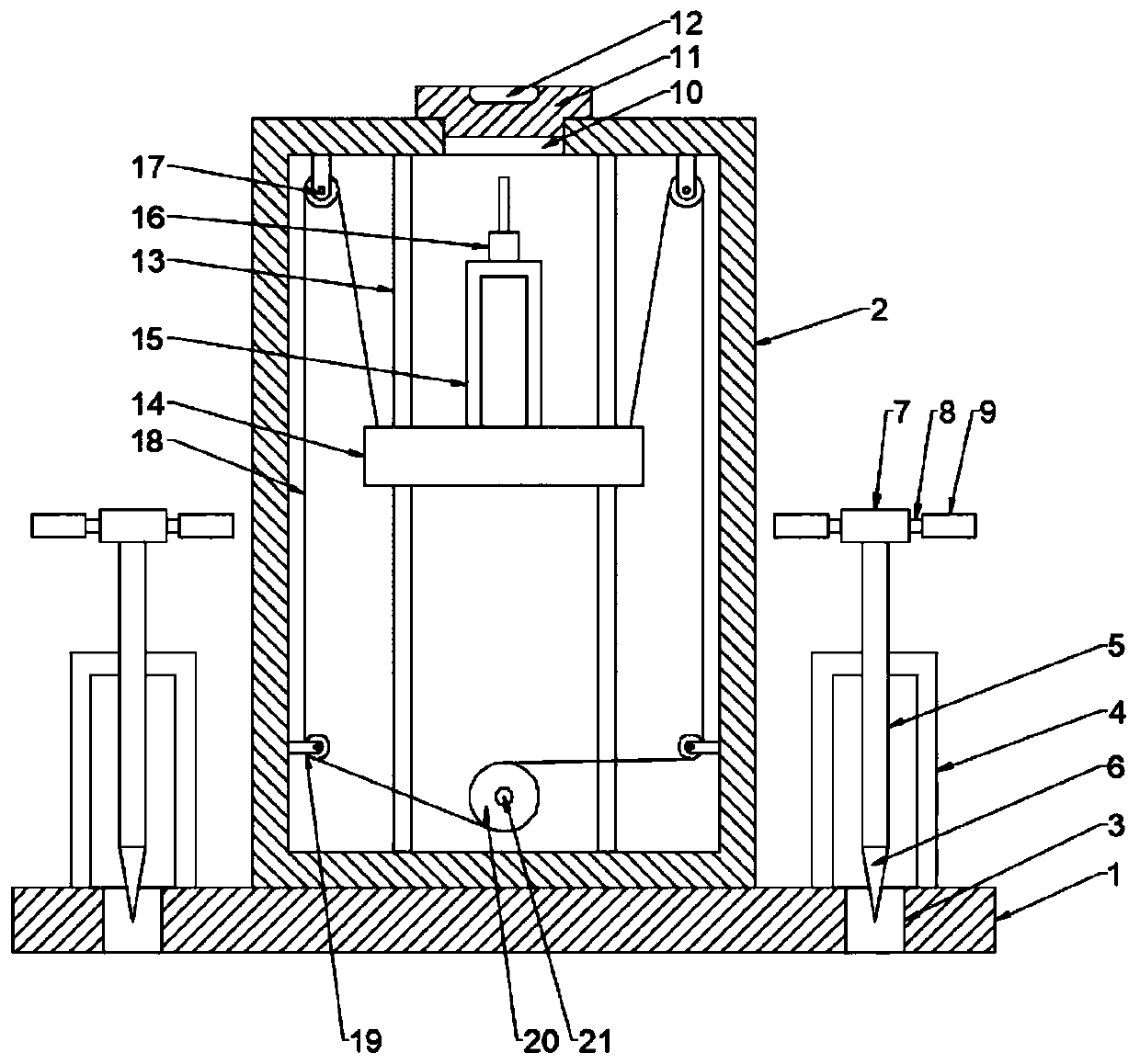
[0029] This embodiment is a further elaboration on the basis of Embodiment 1. The center of the top of the detection box 2 is connected to the probe hole 10, and the inner cavity of the detection box 2 is symmetrically provided with two pairs of guide rails 13 on the front and rear side walls. A lifting seat 14 matched with the probe hole 10 is provided between the guide rails 13 , the guide rail 13 and the lifting seat 14 are slidingly connected, and the lifting seat 14 can slide up and down along the guide rail 13 .

[0030] The center of the top of the lifting base 14 is provided with a pedestal 15 that matches the probe hole 10, the pedestal 15 is a U-shaped structure, and the top of the pedestal 15 is provided with an air detector that matches the probe hole 10. 16. The lifting seat 14 rises along the guide rail 13, so that the base frame 15 passes through the probe hole 10 against the air detector 16, and is exposed to the outside for air detection; after the detection wo...


PUM


Abstract

The invention provides a field air detecting device based on a steady erection technology, and particularly relates to a device for air detecting. The air detecting device comprises a base; the edge of the base is evenly provided with a plurality of through holes; a detecting box is arranged in the center of the top end of the base; the edge of the top end of the base is evenly provided with a plurality of steady rests matched with the through holes; each steady rest is of a U-shaped structure; screws matched with the through holes are embedded in the top walls of the steady rests; the screwsare in threaded connection with the steady rests; the bottom ends of the screws are fixedly connected with anchor thorns; the screws are fixedly connected with rotary plates; the front side wall and the rear side wall of an inner cavity of the detecting box are symmetrically provided with two pairs of guide rails; and a lifting base matched with a probe hole is arranged between all the guide rails. By rotating the rotary plates, the screws are driven to rotate, thus, the height of the anchor thorns is adjusted, by inserting the anchor thorns into the ground, the balance of the base 1 is adjusted through the screws, the mounting stability of the whole device is improved, the device can adapt to mounting and erection in various terrains, and the terrain requirements of the whole device are lowered.

Description

technical field [0001] The invention relates to an air detection device, in particular to an outdoor air detection device based on stable erection technology. Background technique [0002] Air pollution generally refers to the phenomenon that some substances enter the atmosphere due to human activities or natural processes, present sufficient concentrations and reach sufficient time, and thus endanger human comfort, health and welfare or the environment. [0003] In recent years, with the continuous deepening of industrialization and the continuous development of urbanization, the impact on the environment has become more and more obvious, among which air pollution is more obvious. Especially the appearance of smog weather makes the air pollution situation increasingly severe. [0004] In order to monitor and understand the air quality in the field, it is necessary for the staff to set up air detection devices in the field to detect the air. This kind of detection activity ...

Claims


Application Information

Patent Timeline
Patent Type & Authority Applications(China)
IPC IPC(8): F16M7/00F16M11/18G01N33/00
Inventor 不公告发明人
Owner 胡昌兵
Why Eureka
Try Eureka