Lock for a closure element of a real estate property, and corresponding closure element

A closed device, real estate technology, applied in non-mechanical transmission-operated locks, building locks, building fastening devices, etc., can solve the problems of limited service life, frequent maintenance, slow lock action, etc., to simplify the structure and structure. The effect of minimizing size and reducing the number of parts

Inactive Publication Date: 2019-06-04
ROTO FR
View PDF20 Cites 0 Cited by
  • Summary
  • Abstract
  • Description
  • Claims
  • Application Information

AI Technical Summary

Problems solved by technology

[0003] This known lock is slow acting, requires frequent maintenance and has a severely limited lifespan

Method used


Image

  • Lock for a closure element of a real estate property, and corresponding closure element
  • Lock for a closure element of a real estate property, and corresponding closure element
  • Lock for a closure element of a real estate property, and corresponding closure element

Examples


Embodiment Construction

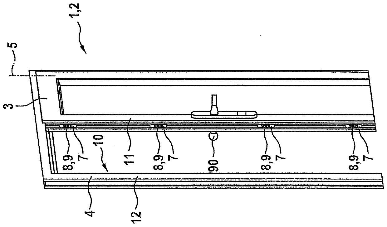
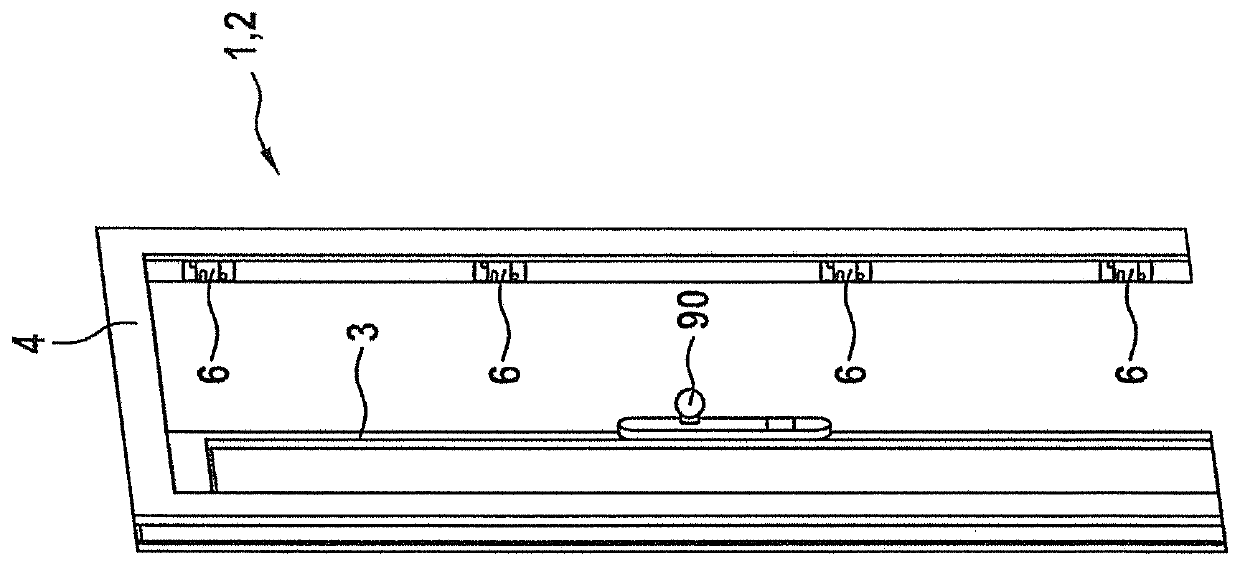
[0047] figure 1 A closing device 2 of the real estate, which is designed as a door 1 , is shown. For example, door 1 is the house door. The door 1 has a leaf 3 which is mounted rotatably about a vertical axis 5 in a frame 4 . door 1 in figure 1 and figure 2 is partially open in which, figure 1 shows the internal view, while the figure 2 An external view is shown. The internal view is a view of the door 1 viewed from the inside of the real estate, and the external view is a view of the door 1 viewed from the outside of the real estate.

[0048] according to figure 2 , the frame 4 is equipped with a plurality of locks 6 . Such as figure 1 As shown, each lock 6 can cooperate with a closing element 7 , which is here located on the leaf 3 . Each closing element 7 has a locking element 8 which is preferably designed as a closing pin 9 . The lock 6 and the closing element 7 are located in the air gap region 10 of the closure device 2 and preferably on those vertical bea...


PUM


Abstract

The invention relates to a lock (6) for a closure element (2) of a real estate property, comprising a pivoting catch (41) on which a spring acts in a preferred direction, a locking member (38), and amanual or mechanical drive device (37). The locking member (38) is designed as a rotary locking member (39) that is driven by the drive device (37) in a circulating manner about a locking member axis(40) in only one rotational direction and comprises multiple locking elements (42) which are offset to one another over the angle at the circumference of the locking member and which interact with thepivoting catch (41) as respective tumblers depending on the rotational angle. Only one of the locking elements (42) constantly acts directly on the pivoting catch (41) for a locking and unlocking process, and the adjacent locking element (42) opposite the rotational direction of the rotary locking member (39) acts on the pivoting catch (41) by rotating the rotary locking member (39) for a subsequent locking and unlocking process.

Description

technical field [0001] The invention relates to a closure device for immovable property, in particular a lock for doors, having a pivoting latch spring-loaded in a preferential direction, a locking member and a manual or mechanical drive. Background technique [0002] Locks of the above-mentioned type are known. It is installed in closures of real estate, in particular doors, and allows locking of the closure. The locking member of the lock is mechanically driven by an electric motor and is used to secure or release the pivoting latch. During locking, the pivoting latch is electrically brought into the locked position. In this case, a corresponding counterpart element (for example a closing plate) is hooked, whereby the closure device is locked. The pivoting latch is prevented from leaving its locking position by means of a locking member driven into a corresponding position. If unlocking is to be achieved, the locking member should be moved to a release position allowin...

Claims


Application Information

Patent Timeline
Patent Type & Authority Applications(China)
IPC IPC(8): E05B47/02E05B63/00E05B63/14E05C3/26E05B17/00E05B47/06
CPCE05B2047/0017E05B2047/0035E05B47/0012E05B47/023E05B47/0607E05B63/0052E05B63/14E05C3/26E05B17/0029E05B2015/0235E05B2047/002E05B2047/0069E05B2063/0026E05B63/24E05C3/24E05B15/0295E05B2047/0067
Inventor P·施塔普夫N·古切
Owner ROTO FR
Why Eureka
Try Eureka