Rotating-centrifugal acceleration takeoff device for light and small unmanned aerial vehicle

A rotating centrifuge and unmanned aerial vehicle technology, applied in the direction of launching/dragging transmission devices, can solve the problems of inconvenient use, long battery life, and less load, and achieve the effect of low operator requirements, simple operation process, and reduced work load

Pending Publication Date: 2019-06-07
HENAN MECHANICAL & ELECTRICAL VOCATIONAL COLLEGE +2
View PDF0 Cites 2 Cited by
  • Summary
  • Abstract
  • Description
  • Claims
  • Application Information

AI Technical Summary

Problems solved by technology

UAVs can be divided into two categories: fixed-wing UAVs and rotary-wing UAVs. Rotary-wing UAVs can take off and land vertically. They have lower requirements on the take-off site and are flexible to use. However, they generally have a long battery life and unstable flight stability. Good, less load and other disadvantages
The fixed-wing UAV has a relatively long battery life and a relatively large load. The flight control is easier than that of the rotary-wing UAV, but the fixed-wing UAV needs a certain speed to take off, and has higher requirements for the take-off site.
[0003] The take-off methods of existing fixed-wing UAVs are mostly taxi take-off, vehicle-mounted take-off, rocket-assisted take-off, etc. These methods either require a long straight runway or a relatively open launch site. many inconveniences

Method used


Image

  • Rotating-centrifugal acceleration takeoff device for light and small unmanned aerial vehicle
  • Rotating-centrifugal acceleration takeoff device for light and small unmanned aerial vehicle
  • Rotating-centrifugal acceleration takeoff device for light and small unmanned aerial vehicle

Examples


Embodiment 2

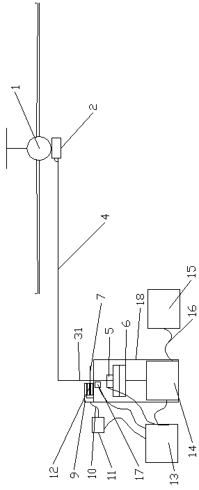
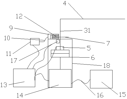
[0039]Embodiment 2, the middle part of the side of the V-shaped card holder 29 is provided with a connecting piece 28, and the fixing of the UAV 1 and the V-shaped card holder 29 is realized by fixing the connecting piece 28 with bolts.

Embodiment 3

[0040] Embodiment 3, the outer end of the rocker arm 33 of the steering gear 20 is provided with a cylindrical protrusion 32, and the cylindrical protrusion 32 is arranged in the sliding inner ring of the elliptical ring 21, and the cylindrical protrusion 32 can slide in the sliding inner ring of the elliptical ring 21.

Embodiment 4

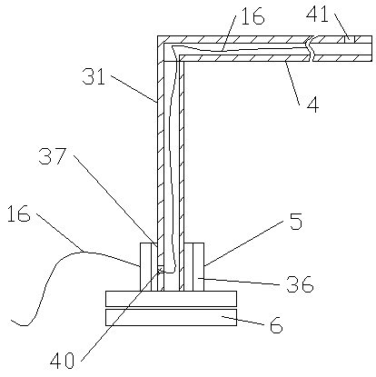
[0041] Embodiment 4, the first straight pipe 31 communicates with the second straight pipe 4, the side wall of the lower end of the first straight pipe 31 is provided with a first wiring hole 40, and the side wall of the outer end of the second straight pipe 4 is provided with The second wiring hole 41 .

[0042] The wire 16 connected between the terminal of the stator 37 inside the rotary connector 5 and the terminal of the steering gear 20 is arranged inside the first straight pipe 31 and the inside of the first straight pipe 31, and the two ends pass through the first wiring hole respectively. 40 is connected to the terminal of the stator 37 , and the second wiring hole 41 is connected to the terminal of the steering gear 20 .


PUM


Abstract

The invention discloses a rotating-centrifugal acceleration takeoff device for a light and small unmanned aerial vehicle. The rotating-centrifugal acceleration takeoff device for the light and small unmanned aerial vehicle comprises a power mechanism, a cantilever structure, a brake device and a releasing device. one end of the cantilever mechanism is connected with the output end of the power mechanism and the other end of the cantilever mechanism is connected with the releasing device, and the unmanned aerial vehicle is provided with a connecting piece the lower part for being fixed on the releasing device; the power mechanism comprises a box-type base, a motor, a power supply, a clutch and a controller, the motor is vertically arranged in the box-type base, an output shaft of the motoris connected with the clutch, and the clutch is connected with a rotating shaft, and the rotating shaft is a hollow first straight pipe. By accelerating the rotation of a second straight tube, then, when the linear speed of the outer end of the second straight pipe reaches or exceeds the minimum flight speed of the unmanned aerial vehicle, the unmanned aerial vehicle is released for takeoff, the accelerated linear motion of the unmanned aerial vehicle is converted into rotating motion, the rotating-centrifugal acceleration takeoff device has low requirements on the takeoff site and can be usedas the takeoff device of the light and small rotating in most cases, and is convenient and flexible.

Description

technical field [0001] The invention relates to the technical field of take-off devices for unmanned aerial vehicles, in particular to a rotary centrifugal acceleration take-off device for light and small unmanned aerial vehicles. Background technique [0002] In recent years, drones have developed rapidly. UAVs can be divided into two categories: fixed-wing UAVs and rotary-wing UAVs. Rotary-wing UAVs can take off and land vertically. Good, less load and other shortcomings. The fixed-wing UAV has a relatively long battery life and a relatively large load, and its flight control is easier than that of a rotary-wing UAV. However, a fixed-wing UAV needs a certain speed to take off, and has higher requirements for the take-off site. [0003] The take-off methods of existing fixed-wing UAVs are mostly taxi take-off, vehicle take-off, rocket-assisted take-off, etc. These methods either require a long straight runway or a relatively open launch site, which is useful to use. A lo...

Claims


Application Information

Patent Timeline
Patent Type & Authority Applications(China)
IPC IPC(8): B64F1/04
Inventor 付毅峰陈海峰许智辉岳艳阁彭浩马鹏博张圆圆伦丽
Owner HENAN MECHANICAL & ELECTRICAL VOCATIONAL COLLEGE
Why Eureka
Try Eureka