
A Micro-displacement Amplifying Mechanism

A technology of amplifying mechanism and micro-displacement, which is applied in the direction of generator/motor, piezoelectric effect/electrostrictive or magnetostrictive motor, electrical components, etc. Sex and other issues, to achieve the effect of compact structure, easy machining, and uniform distribution

Active Publication Date: 2020-08-21
CHANGCHUN INST OF OPTICS FINE MECHANICS & PHYSICS CHINESE ACAD OF SCI
View PDF7 Cites 0 Cited by
  • Summary
  • Abstract
  • Description
  • Claims
  • Application Information

AI Technical Summary

Problems solved by technology

This arrangement is special, not universally applicable, and cannot adapt to the arrangement of more levels of levers

Method used


Image

  • A Micro-displacement Amplifying Mechanism
  • A Micro-displacement Amplifying Mechanism
  • A Micro-displacement Amplifying Mechanism

Examples


Embodiment Construction

[0021] The following will clearly and completely describe the technical solutions in the embodiments of the present invention with reference to the accompanying drawings in the embodiments of the present invention. Obviously, the described embodiments are only some of the embodiments of the present invention, not all of them. Based on the embodiments of the present invention, all other embodiments obtained by persons of ordinary skill in the art without making creative efforts belong to the protection scope of the present invention.

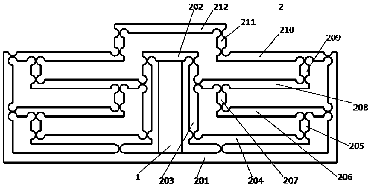
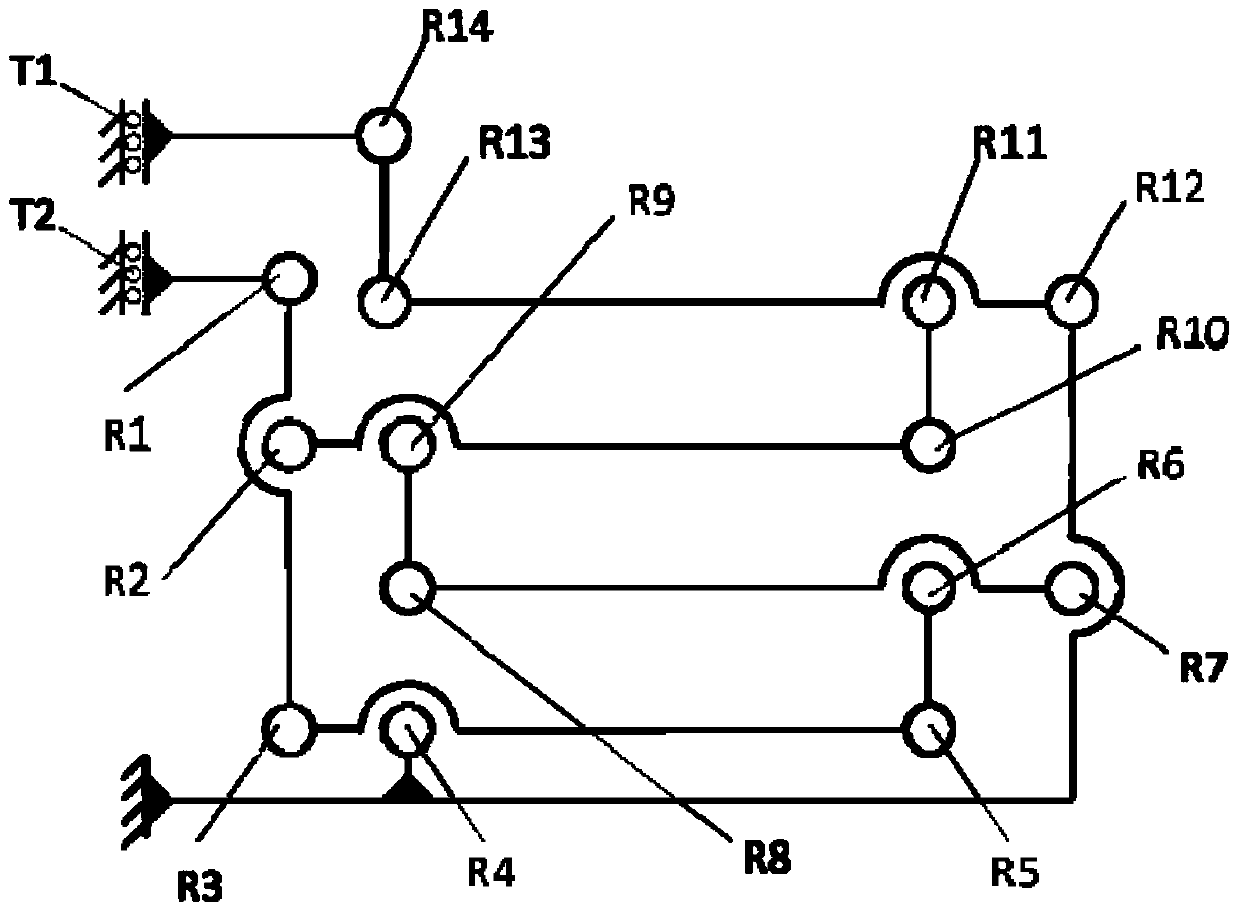
[0022] see figure 1 , is a structural schematic diagram of the micro-displacement amplification mechanism 2 provided by the embodiment of the present invention, including: a piezoelectric ceramic driver 1, a displacement input terminal 202 fixedly connected to the piezoelectric ceramic driver 1, a displacement output terminal 212 and a multi-stage lever, The multi-stage lever includes several levers connected in sequence. The connection relation...


PUM


Abstract

The micro-displacement amplifying mechanism provided by the present invention includes: a piezoelectric ceramic driver, a displacement input end, a displacement output end and a multi-level lever. The vertical axis where the piezoelectric ceramic driver is located is symmetrically arranged with respect to the axis of symmetry. Each level of the multi-level lever has 1-2 input ends and at least one output end, and each input end of each level of lever is connected to a certain front-end. One output end or displacement input end of the first-stage lever, and the output end of the last-stage lever is connected to the displacement output end. The micro-displacement amplifying mechanism provided by the present invention, because the multi-stage lever adopts a series-parallel hybrid connection scheme, which is different from the traditional one. The multi-level levers are simply stacked in series, so compared with the prior art, they can achieve a larger magnification in a smaller space, and the structure is arranged in a reasonable and orderly manner, the structure is compact, the limited space is fully utilized, and the flexible hinges are evenly distributed , which is convenient for machining.

Description

technical field [0001] The invention relates to the technical field of precision machinery, in particular to a micro-displacement amplification mechanism. Background technique [0002] In recent years, piezoelectric ceramics have been widely researched and applied in precision optomechanical systems due to their advantages of high resolution, fast response and large output force. However, the output displacement of piezoelectric ceramics is about one-thousandth of its superposition length, so that its application range can only be concentrated in the occasions of a few microns to tens of microns. In order to apply piezoelectric ceramics to driving applications with larger strokes, it is necessary to set up a displacement amplification mechanism. [0003] The flexible hinge mechanism is the most commonly used piezoelectric ceramic displacement amplification mechanism. According to its structural form and principle, it mainly includes triangle type, lever type, and parallel f...

Claims


Application Information

Patent Timeline
Patent Type & Authority Patents(China)
IPC IPC(8): H02N2/02H02N2/04
Inventor 张丽敏王建立赵勇志宋云夺
Owner CHANGCHUN INST OF OPTICS FINE MECHANICS & PHYSICS CHINESE ACAD OF SCI
Learn More