Device and method for capturing eel in sea
A technology for capturing device and eel, which is applied in fishing, application, animal husbandry, etc., can solve the problems of high production cost and high labor intensity, and achieve the effect of low production cost, less labor, and reduced labor cost.
- Summary
- Abstract
- Description
- Claims
- Application Information
AI Technical Summary
Problems solved by technology
Method used
Image
Examples
Embodiment 1
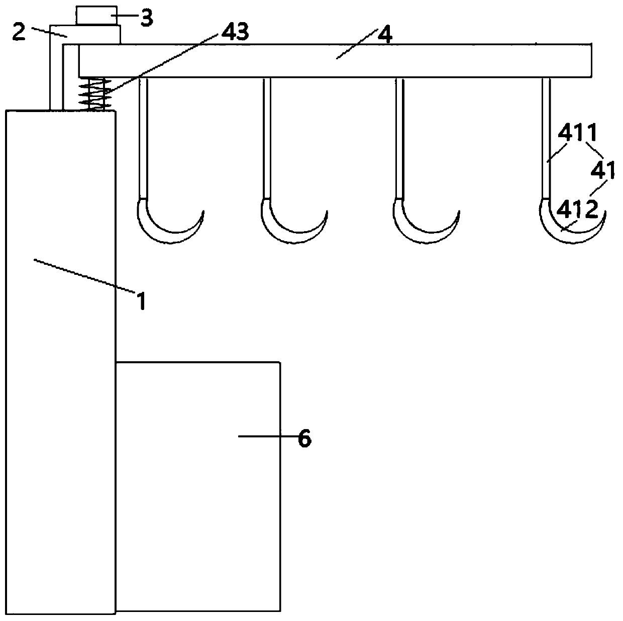
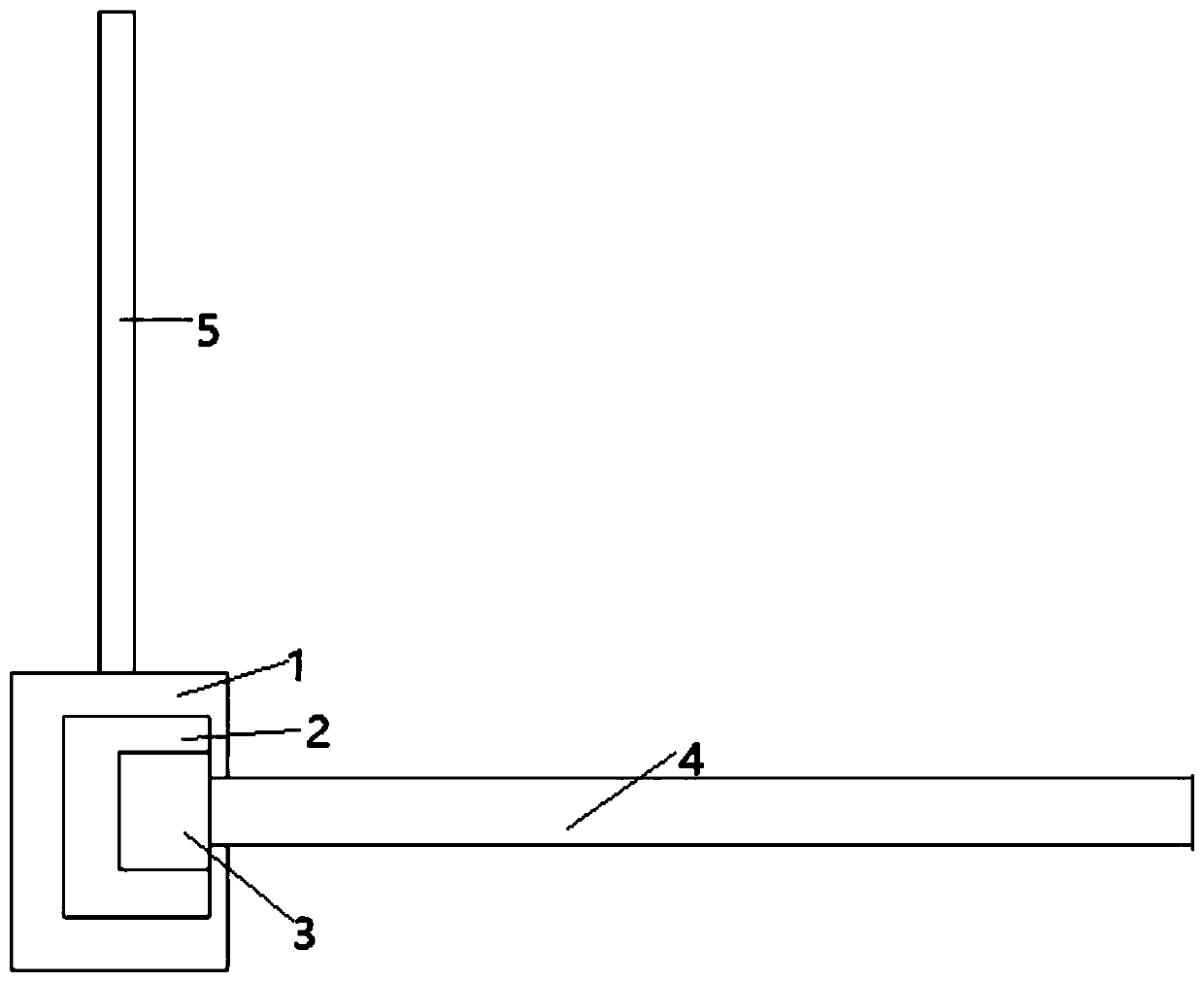
[0042] like figure 1 The illustrated embodiment is a device for catching eels in the sea, comprising a column 1 located on the seabed, a support frame 2 located at the upper end of the column, a first motor 3 located on the support frame, and a cross bar 4 connected to the first motor , 5 suspension hooks 41 located on the cross bar, a strip vertical bar 5 located on one side of the column, an eel storage box 6, a lifting clamp 7 located in the eel storage box, and a bait supply mechanism 8 close to the eel storage box ; The strip vertical rod is provided with 5 electromagnets 51, such as Image 6 As shown, the hook includes a vertical bar 411 made of iron material, and a hook body 412 arranged at the lower end of the vertical bar. The hook body includes an arc-shaped sleeve 4121 and an arc-shaped hook 4122 with one end extending into the arc-shaped sleeve. The return spring 41222 between the inwardly bent annular edge 41211 at the lower end of the arc-shaped sleeve and the b...
Embodiment 2
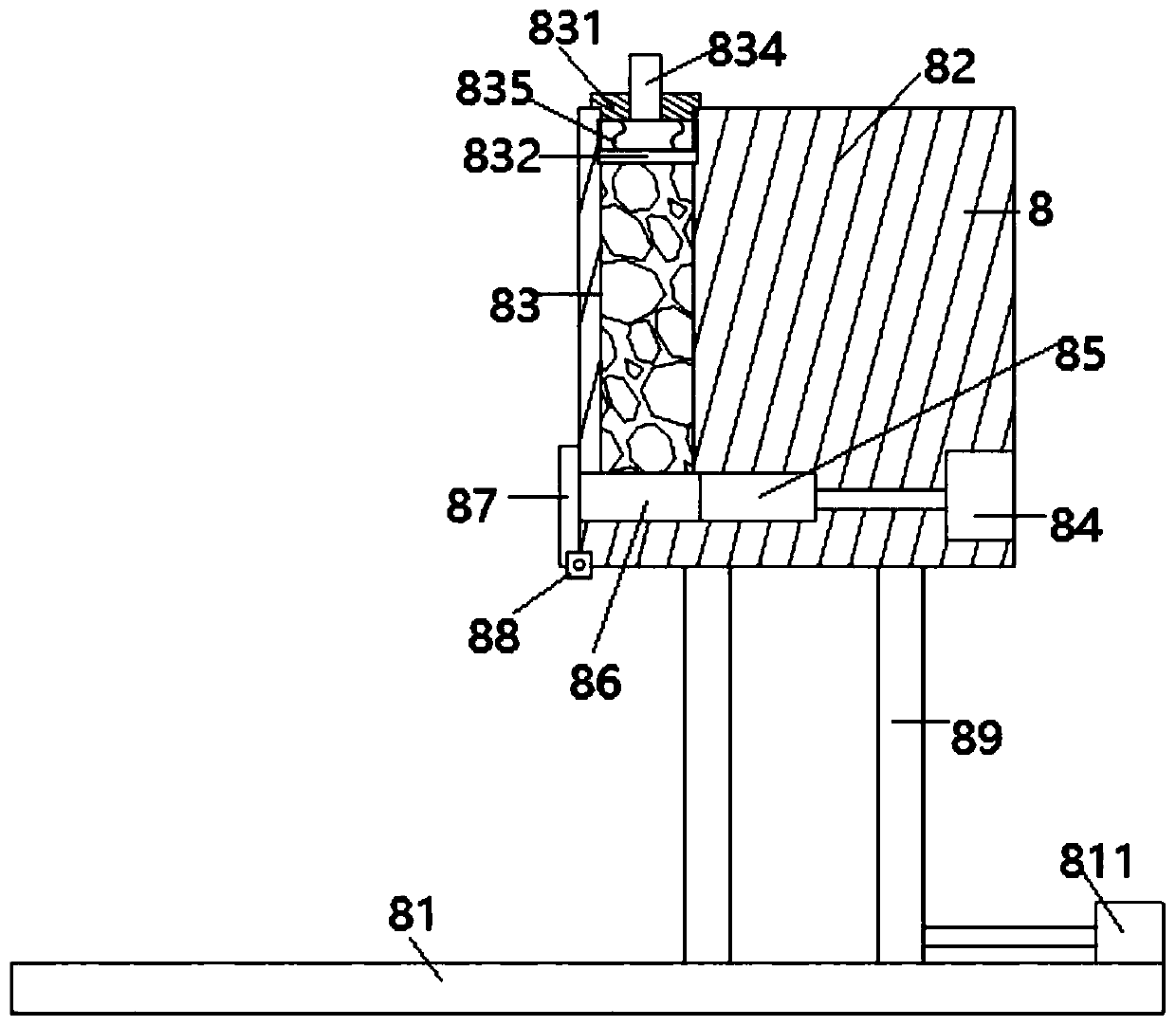
[0055] Embodiment 2 includes all structure and method parts of embodiment 1, such as image 3 As shown, the bait supply mechanism of Embodiment 2 includes two guide rails 81 located on the seabed, and a strip seat 82 above the two guide rails; five vertical cavities 83 and five first cylinders 84 are provided on the strip seat The telescopic rod of each first cylinder is connected with the extruding block 85, and the lower end of each vertical chamber is provided with a transverse channel 86, and each extruding block is respectively stretched into each transverse channel, and the left part of the strip seat is provided with a cover plate 87, the cover plate is connected with the strip seat through the rotating shaft, and the rotating shaft is connected with the second motor 88; the upper end of the vertical cavity is provided with a cover 831, and the vertical cavity is provided with a pressing plate 832, and each cover is provided with a The trachea 834 connected with the sec...
Embodiment 3
[0060] Embodiment 3 includes all structure and method parts of embodiment 1, as Figure 9 As shown, the heating mechanism includes a heating box 2031, a heater 2032 arranged in the heating box, two solenoid valves 2033 respectively arranged on the water inlet and the water outlet of the heating box, and three annular rings surrounding the column connected to the water outlet. Pipe 2034; each annular pipe is provided with a flexible shaft 2035, each flexible shaft is provided with a helical blade 2037, the heating box is provided with a third motor 2036 for driving the flexible shaft to rotate, each annular pipe is provided with a There are multiple drainage holes, and the diameter of the drainage hole closer to the water outlet is smaller, such as Figure 7 As shown, the two solenoid valves and each third motor are electrically connected to the controller.
[0061] Step (6-1) of Example 1 is replaced by the following steps:
[0062] The temperature sensor detects the seawate...
PUM
 Abstract
Description
Claims
Application Information
 - R&D
- Intellectual Property
- Life Sciences
- Materials
- Tech Scout
- Unparalleled Data Quality
- Higher Quality Content
- 60% Fewer Hallucinations
Browse by: Latest US Patents, China's latest patents, Technical Efficacy Thesaurus, Application Domain, Technology Topic, Popular Technical Reports.
© 2025 PatSnap. All rights reserved.Legal|Privacy policy|Modern Slavery Act Transparency Statement|Sitemap|About US| Contact US: help@patsnap.com


