A new energy battery installation structure

An installation structure and new energy technology, applied in electric power devices, battery/battery traction, charging stations, etc., can solve problems such as inconvenient replacement, battery impact, troublesome disassembly and assembly, and achieve stable lifting process and high safety. , the effect of battery stability

Active Publication Date: 2020-07-24
HANGZHOU DEBIAO NEW ENERGY TECH CO LTD
View PDF8 Cites 0 Cited by
  • Summary
  • Abstract
  • Description
  • Claims
  • Application Information

AI Technical Summary

Problems solved by technology

[0002] New energy vehicles are becoming more and more popular in daily life, especially electric vehicles are powered by vehicle-mounted power supplies, and use motors to drive wheels, which are energy-saving and environmentally friendly. Electric vehicles need to be equipped with new energy batteries, and new energy batteries are large in size. The energy battery is usually flat and installed on the bottom of the vehicle body through a fixed structure. In order to reduce the waiting time for charging the vehicle, the charging station currently provides battery replacement services. The owner can replace the exhausted battery with the saturated battery, but Due to the cumbersome disassembly and assembly of the fixed structure of the battery on the vehicle body, the replacement is not convenient enough, and the current battery is usually directly fixed and installed, and the bumps and vibrations during the driving of the vehicle will be transmitted to the battery, which will have an impact on the battery. Affect battery stability

Method used


Image

  • A new energy battery installation structure
  • A new energy battery installation structure
  • A new energy battery installation structure

Examples


Embodiment Construction

[0030] The following are specific embodiments of the present invention and in conjunction with the accompanying drawings, the technical solutions of the present invention are further described, but the present invention is not limited to these embodiments.

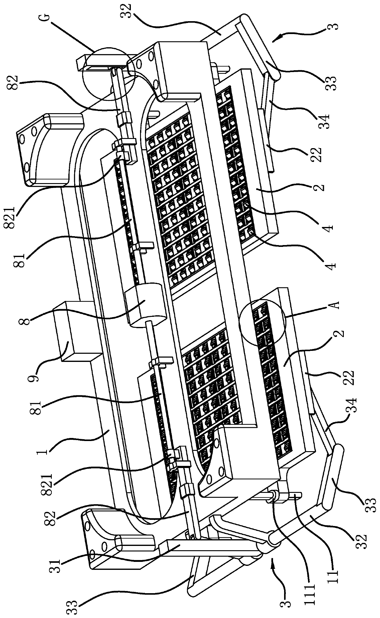
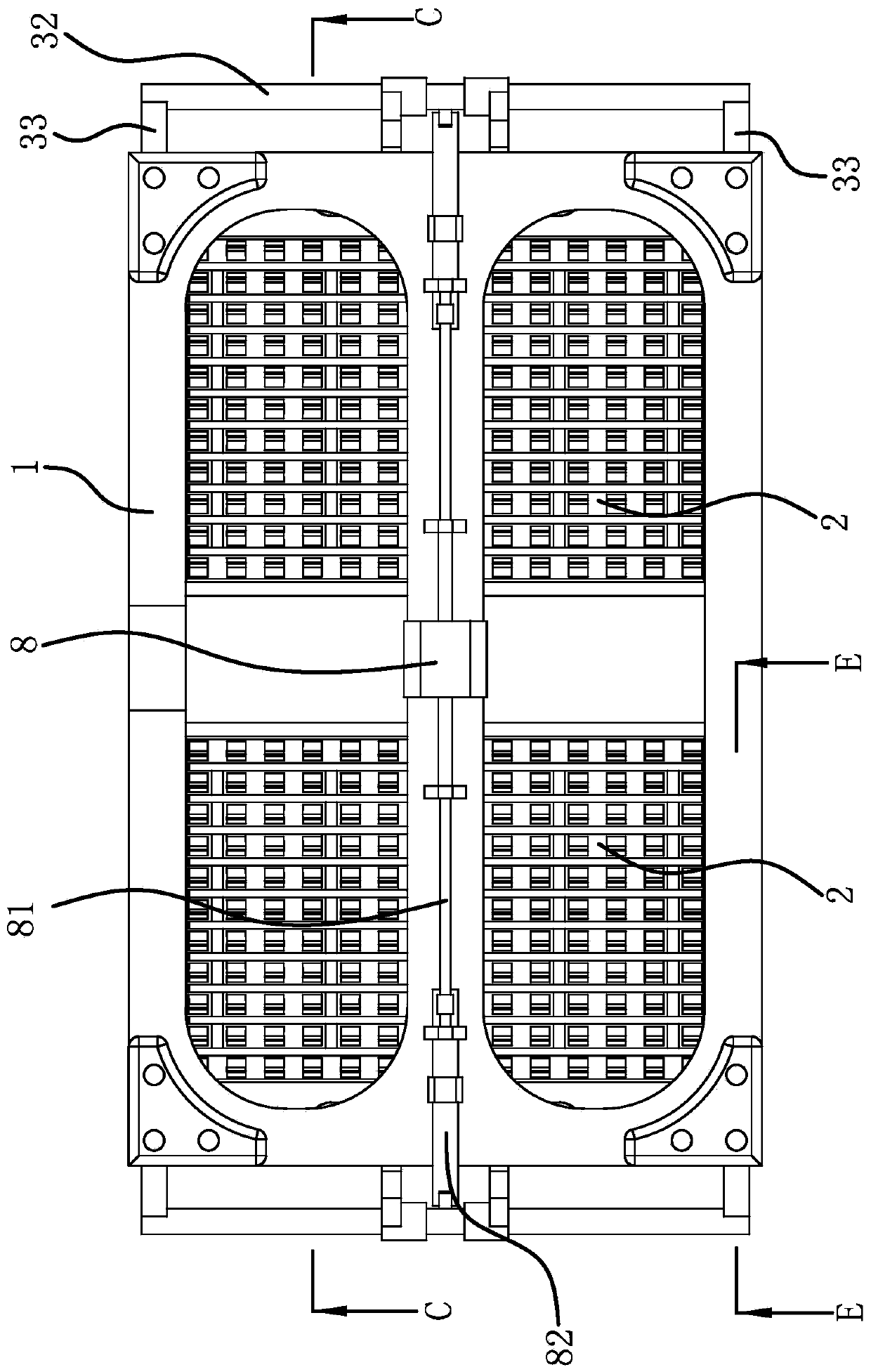
[0031] Such as figure 1 , figure 2 As shown, a new energy battery installation structure includes a fixed frame 1 for fixing on the vehicle body and two support plates 2 for placing batteries. 1, both sides of the fixed frame 1 are hinged with driving arms 3, the driving arms 3 are bent and set, and the upper end of the driving arm 3 is higher than the fixed frame 1, and the lower ends of the two driving arms 3 extend to the bottom of the two support plates 2 respectively It is also slidably connected to the two support plates 2 in the lateral direction, and the lower end of the drive arm 3 can rotate relative to the support plate 2. The fixed frame 1 is provided with a driver that can drive the two drive arms 3 to swing...


PUM


Abstract

The invention provides a new-energy battery mounting structure, and belongs to the technical field of new-energy vehicles. The problem is solved that current new-energy batteries are not stable duringuse. The new-energy battery mounting structure includes a fixing frame and two support plates and is characterized in that the support plates are slidably connected with the fixing frame, drive armsare hinged to the two sides of the fixing frame, the lower ends of the drive arms can rotate relative to the support plates, a drive part is arranged on the fixing frame, a plurality of space notchesare formed in the upper side face of each support plate, damping elastic pieces are arranged inside the space notches, transmission mechanisms which can make the damping elastic pieces protrude out ofthe space notches and abut against the lower side face of a battery when the support plates rise to an upper limit position are arranged between the drive arms and the damping elastic pieces, and a positioning mechanism is arranged on each support plate. The new-energy battery mounting structure can make the battery fixed more stably, and the battery is safer to mount and dismount.

Description

technical field [0001] The invention belongs to the technical field of new energy vehicles and relates to a new energy battery installation structure. Background technique [0002] New energy vehicles are becoming more and more popular in daily life, especially electric vehicles are powered by vehicle-mounted power supplies, and use motors to drive wheels, which are energy-saving and environmentally friendly. Electric vehicles need to be equipped with new energy batteries, and new energy batteries are large in size. The energy battery is usually flat and installed on the bottom of the vehicle body through a fixed structure. In order to reduce the waiting time for charging the vehicle, the charging station currently provides battery replacement services. The owner can replace the exhausted battery with the saturated battery, but Due to the cumbersome disassembly and assembly of the fixed structure of the battery on the vehicle body, the replacement is not convenient enough, a...

Claims


Application Information

Patent Timeline
Patent Type & Authority Patents(China)
IPC IPC(8): B60L50/64B60L53/80B60K1/04
CPCY02T10/70Y02T10/7072
Inventor 李坚忠
Owner HANGZHOU DEBIAO NEW ENERGY TECH CO LTD
Why Eureka
Try Eureka