
High-frequency test bench for QFN chip

A technology of test socket and chip, which is applied in the direction of electronic circuit testing, measuring electricity, measuring devices, etc., and can solve the problems of long channel, low quality of high-frequency signal transmission, high probe inductive reactance, capacitive reactance, etc.

Pending Publication Date: 2019-06-14
SUZHOU UIGREEN MICRO & NANO TECH CO LTD
View PDF0 Cites 1 Cited by
  • Summary
  • Abstract
  • Description
  • Claims
  • Application Information

AI Technical Summary

Problems solved by technology

[0002] With the rapid development of chip technology, the existing high-frequency test socket is a spring probe type test socket, which has a long signal transmission channel, and the inductive reactance and capacitive reactance of the probe itself are relatively high, which is not good for the transmission quality of high-frequency signals. high
With the increase of the signal transmission frequency in the current chip, the traditional socket structure based on the spring probe test has encountered severe challenges, and it is necessary to develop a new structure of test probes and corresponding test sockets to meet the development needs.

Method used


Image

  • High-frequency test bench for QFN chip
  • High-frequency test bench for QFN chip
  • High-frequency test bench for QFN chip

Examples


Embodiment Construction

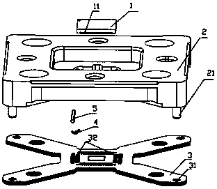
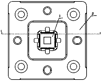
[0018] The technical scheme of the present invention is specifically described below in conjunction with the embodiments. The present invention discloses a high-frequency test socket for a QFN chip. Figure 1-Figure 4 As shown, it includes at least two layers of test main boards 3 superimposed on each other, and a guide plate 2 arranged above the test main board 3. In the present invention, there are four test main boards 3, and adjacent test main boards 3 are glued together. Knots connect to form a whole. The test main board 3 is provided with four ends, and each end is provided with a socket hole 31 .

[0019] The guide platen 2 is made of polyamide-imide material, and a guide column 21 is provided at the bottom, and the guide platen 2 and the test main board 3 are plugged and connected through the guide column 21 . The cross-section of the test main board 3 in the present invention is in the shape of "x", the middle part of the test main board 3 is a detection part, and th...


PUM


Abstract

The invention provides a high-frequency test bench for a QFN chip. The high-frequency test bench comprises at least two layers of mutually overlapped test main boards, and a guiding pressing plate arranged on the test main boards; a holding through hole cavity for holding the QFC chip is formed in the middle of the guiding pressing plate; the middles of the test main boards are detection parts, and each detection part is located below the holding through cavity; detection hole slots are formed on the detection parts, and probes connected with the QFN chips are arranged in the detection hole slots, and the probes are arranged in a sheet shape; the detection hole slots on the upper layer test main body and the lower lowery test main board are staggered, and two ends of each probe are locatedin the detection hole slots are different layers; the contact points at the bottom of the QFN chip are in contact connection with the test main boards through the probes. The test bench provided by the invention has the advantages that the test bench has a transmission capacity of a high-frequency signal, the high-frequency connection between the QFN chip and a circuit board is guarantee under the condition of guaranteeing the bearing of relative large current.

Description

technical field [0001] The invention belongs to the technical field of electronic components, and in particular relates to a high-frequency test seat. Background technique [0002] With the rapid development of chip technology, the existing high-frequency test socket is a spring probe type test socket, which has a long signal transmission channel, and the inductive reactance and capacitive reactance of the probe itself are relatively high, which is not good for the transmission quality of high-frequency signals. high. With the increase of the signal transmission frequency in the current chip, the traditional socket structure based on the spring probe test has encountered severe challenges, and it is necessary to develop a new structure of test probes and corresponding test sockets to meet the development needs. Contents of the invention [0003] In order to solve the deficiencies of the prior art, the present invention provides a high-frequency test socket. [0004] The ...

Claims


Application Information

Patent Timeline
Patent Type & Authority Applications(China)
IPC IPC(8): G01R31/28G01R1/04G01R1/067
Inventor 钱晓晨骆兴顺
Owner SUZHOU UIGREEN MICRO & NANO TECH CO LTD
Learn More