Music therapy type reading support
A technology of music and cantilever brackets, which is applied in the field of music therapy reading brackets, and can solve the problems of not having and not being able to combine music therapy
- Summary
- Abstract
- Description
- Claims
- Application Information
AI Technical Summary
Problems solved by technology
Method used
Image
Examples
Embodiment 1
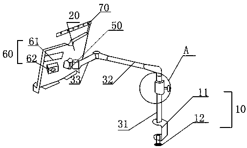
[0036] In order to solve the problem that the book holder in the prior art is only suitable for placing on a horizontal desktop and has a narrow application range, the present invention provides a figure 1 with figure 2 Music Therapy Reading Stand shown. The music therapy type reading support includes a base clamp 10, a cantilever support and a reading support 20, the base clamp 10 is fixed on the bottom end of the cantilever support, and is used to fix the cantilever support on a supporting object, and the reading support 20 is fixedly connected with the cantilever support for Regularly read publications.
[0037]The back side of the reading stand 20 of the music therapy type reading stand has a power supply, a circuit board and a music therapy module 60, and the music therapy module includes an operation panel 61, a processor, a storage unit for treating songs and an audio player 62, and the power supply passes through the circuit board. The drive circuit supplies power t...
Embodiment 2
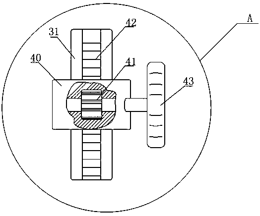
[0041] The difference between this embodiment and Embodiment 1 is that: the cantilever support of the music therapy type reading support includes a lifting rod 31, a first horizontal rod 32 and a second horizontal rod 33 connected in sequence, and the base clamp 10 includes a U-shaped fixing part 11 and adjusting bolt 12, the U-shaped fixed part 11 is installed on the bottom of the elevating rod 31, and the elevating rod 31 is fastened on the supporting object by the adjusting bolt 12 installed on the bottom of the U-shaped fixed part 11.
[0042] The first horizontal rod 32 is perpendicular to the elevating rod 31, and the rear end of the first horizontal rod 32 is connected with the top end of the elevating rod 31 by an L-shaped joint, and the front end of the first horizontal rod 32 is hinged with one end of the second horizontal rod 33. The other end of the two horizontal rods 33 is connected with the back of the reading frame 20 through the damping rotating shaft 50 .
[...
Embodiment 3
[0050] The difference between this embodiment and embodiment 2 is:
[0051] Such as Figure 4 with Figure 5 As shown, the damping rotating shaft 50 includes: a rotating shaft sleeve 51, a rotating shaft 52 arranged in the rotating shaft sleeve 51, the rotating shaft 52 includes a damping part 521 and a connecting part 522 fixedly connected together; the shape of the damping part 521 is cylindrical, and passes through In the inner hole of the rotating shaft sleeve 51, a plurality of first protrusions 523 are arranged on the surface of the damping part 521, and the first protrusions 523 are evenly distributed in the axial direction of the damping part 521, and the top ends of each first protrusion 523 are on the same On the virtual circle, the diameter of the virtual circle is larger than the diameter of the inner hole of the rotating shaft sleeve 51 , and the material of the first protrusion 523 is elastic material.
[0052] The shaft sleeve and the connecting part are respe...
PUM
 Abstract
Description
Claims
Application Information
 - R&D
- Intellectual Property
- Life Sciences
- Materials
- Tech Scout
- Unparalleled Data Quality
- Higher Quality Content
- 60% Fewer Hallucinations
Browse by: Latest US Patents, China's latest patents, Technical Efficacy Thesaurus, Application Domain, Technology Topic, Popular Technical Reports.
© 2025 PatSnap. All rights reserved.Legal|Privacy policy|Modern Slavery Act Transparency Statement|Sitemap|About US| Contact US: help@patsnap.com


