
Remote monitoring equipment for power electronic transformers

A technology of power electronics and remote monitoring, applied in the direction of circuit devices, electrical components, etc.

Active Publication Date: 2019-06-21
BEIJING AEROSPACE GUANGHUA ELECTRONIC TECH CO LTD +1
View PDF1 Cites 2 Cited by
  • Summary
  • Abstract
  • Description
  • Claims
  • Application Information

AI Technical Summary

Problems solved by technology

At present, there is no special equipment on the market that can monitor the internal and external states of power electronic transformers in real time and in all directions to ensure the normal operation of the whole machine.

Method used

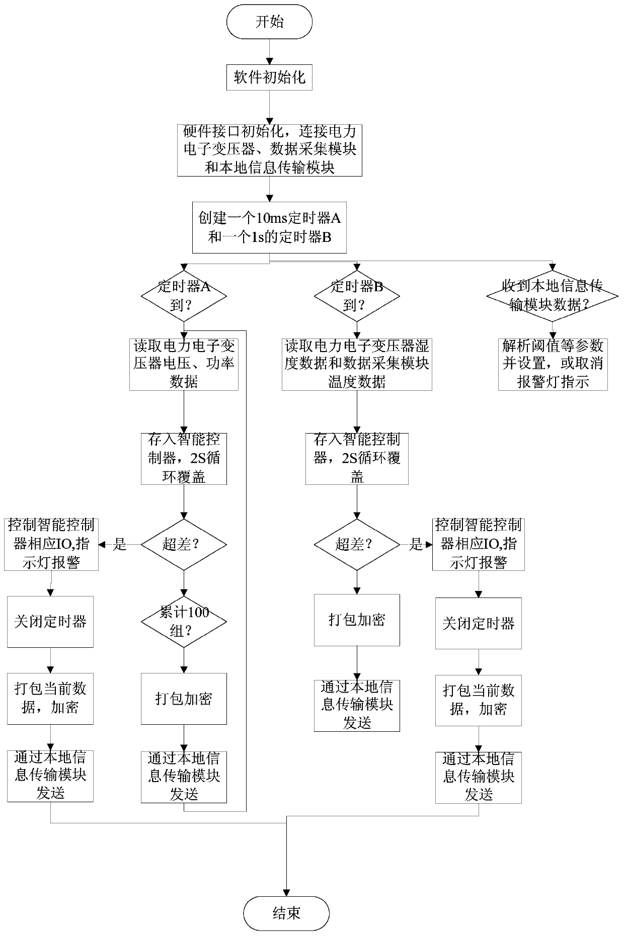
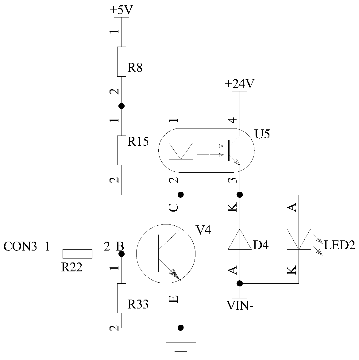

Image

  • Remote monitoring equipment for power electronic transformers
  • Remote monitoring equipment for power electronic transformers
  • Remote monitoring equipment for power electronic transformers

Examples


Embodiment Construction

[0034] Exemplary embodiments of the present disclosure will be described in more detail below with reference to the accompanying drawings. Although exemplary embodiments of the present disclosure are shown in the drawings, it should be understood that the present disclosure may be embodied in various forms and should not be limited by the embodiments set forth herein. Rather, these embodiments are provided for more thorough understanding of the present disclosure and to fully convey the scope of the present disclosure to those skilled in the art. It should be noted that, in the case of no conflict, the embodiments of the present invention and the features in the embodiments can be combined with each other. The present invention will be described in detail below with reference to the accompanying drawings and examples.

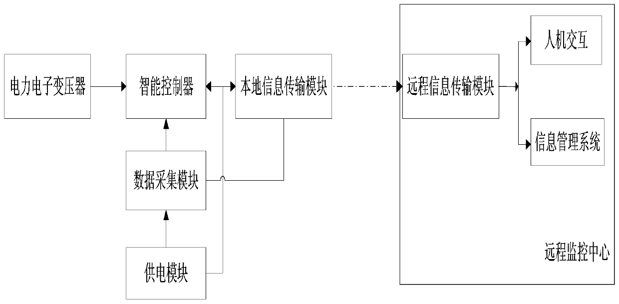
[0035] figure 1 It is a block diagram of the power electronic transformer remote monitoring equipment of the present invention. Such as figure 1 As shown, ...


PUM


Abstract

The invention provides remote monitoring equipment for power electronic transformers. The equipment comprises an intelligent controller, a power supply module, a data acquisition module, a local information transmission module and a remote monitor center. Aiming at the differences of the present similar products, the equipment provided by the invention has the characteristics of being high in integrity, safe, reliable and high in timeliness, and is capable of realizing remote monitor for key equipment states during the operation of the power electronic transformers, carrying out automatic warning, transmitting state information in real time and obtaining equipment fault states in real time, thereby improving the monitor ability and efficiency and ensuring the work safety of the equipment.

Description

technical field [0001] The invention relates to the energy field of the national grid, in particular to a remote monitoring device for a power electronic transformer. Background technique [0002] The power grid is an important part related to the lifeline of the national economy and national energy security. The political and economic significance of power electronic transformers in power grid equipment as a new type of power electronic equipment is self-evident. At present, there is no special equipment on the market that can monitor the internal and external states of power electronic transformers in real time and in all directions to ensure the normal operation of the whole machine. Therefore, it is particularly urgent to develop a kind of remote monitoring equipment of this type, which is the original intention of the present invention. Contents of the invention [0003] The technical problem to be solved by the present invention is to overcome the deficiencies of th...

Claims


Application Information

Patent Timeline
Patent Type & Authority Applications(China)
IPC IPC(8): H02J13/00
Inventor 陈娜辛瑞红张晓友李飞杜文洲王晓亮曹文政弓新月李娟
Owner BEIJING AEROSPACE GUANGHUA ELECTRONIC TECH CO LTD
Learn More