Supercharge Your Innovation With Domain-Expert AI Agents!

Method for manufacturing metal member

A manufacturing method and metal technology, applied in the direction of metal processing equipment, etc., can solve the problems of thin plate thickness and curvature radius, etc., and achieve the effect of reducing the possibility

Active Publication Date: 2019-06-21
KANEMITSU KK
View PDF10 Cites 0 Cited by
  • Summary
  • Abstract
  • Description
  • Claims
  • Application Information

AI Technical Summary

Problems solved by technology

Metal members manufactured in this way have a problem that the plate thickness of the root portion of the cylindrical portion tends to become thinner.
In addition, the metal member manufactured in this way has a problem that the portion corresponding to the root portion of the inner peripheral surface of the cylindrical portion becomes a curved surface with a large radius of curvature.

Method used


Image

  • Method for manufacturing metal member
  • Method for manufacturing metal member
  • Method for manufacturing metal member

Examples


Embodiment Construction

[0029] Embodiments of the present invention will be described below with reference to the drawings. In the following description, the same reference numerals are assigned to the same components. Their names and functions are also the same. Therefore, a detailed description thereof will not be repeated.

[0030] (Explanation of process)

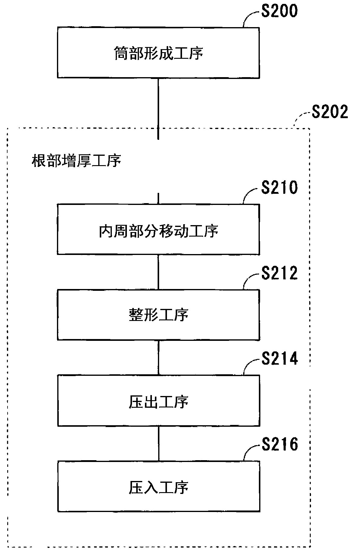
[0031] figure 1 It is a figure which shows the process included in the manufacturing method of the metal member of this embodiment. based on figure 1 The manufacturing method of the metal member of this embodiment is demonstrated. The manufacturing method of the metal member of this embodiment includes the cylindrical part forming process S200, and the root part thickening process S202. In the case of the present embodiment, the root thickening step S202 includes an inner peripheral part moving step S210, a shaping step S212, a pushing step S214, and a pushing step S216.

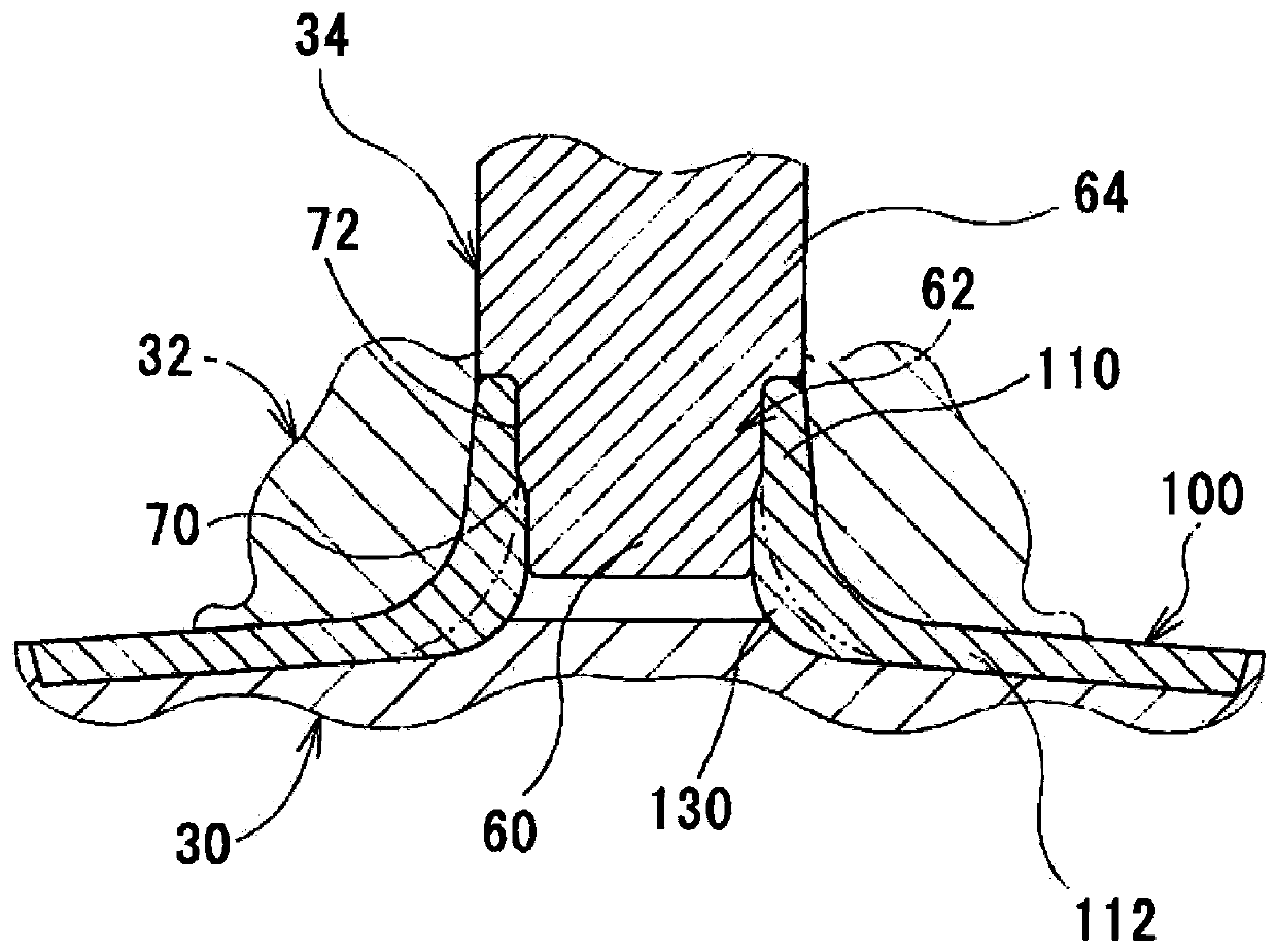
[0032] Figure 2 to Figure 6 It is a figure of the mold and t...


PUM


Abstract

The present invention reduces the possibility of wrinkles forming between a cylindrical part and the periphery of a base thereof. A method for manufacturing a metal member is provided with a cylindrical part forming step S200 and a base wall thickness increasing step S202. The cylindrical part forming step S200 comprises forming a cylindrical part in a metal plate-shaped material. The base wall thickness increasing step S202 comprises increasing the wall thickness of a base portion of the cylindrical part. The base wall thickness increasing step S202 has an internal-peripheral-portion movementstep S210 and a push-out step S214. In the internal-peripheral-portion movement step S210, a punch causes an internal peripheral portion on a distal-end side of the cylindrical part to move toward aninternal peripheral portion on the base side. In the push-out step S214, the punch pushes out the moved portion of the cylindrical part moved in the internal-peripheral-portion movement step S210 inthe opposite direction from the protrusion direction of the cylindrical part as viewed from the periphery of the base of the cylindrical part in a state in which the periphery of the base of the cylindrical part is interposed between a female die and a pressing die.

Description

technical field [0001] This invention relates to the manufacturing method of a metal member. Background technique [0002] A metal member having a cylindrical portion and a plate-like portion provided at one end of the base of the cylindrical portion is known. Various components are manufactured by subjecting the member to further processing. Such a metal member is manufactured by performing plastic working on a metal plate. An example of its production method includes the following three steps. The first step is a step of deep-drawing the metal plate. As a result, convex portions are formed on the plate material. The second step is a step of opening a hole at the tip of the protrusion. The third step is a step of performing plastic working on the perforated convex portion. Thereby, this convex part becomes a cylindrical part. The metal member manufactured in this way has a problem that the plate thickness of the root part of a cylindrical part becomes thin easily. I...

Claims


Application Information

Patent Timeline
IPC IPC(8): B21D19/08
CPCB21D19/08B21J5/06B21J5/08
Inventor 藤井直树
Owner KANEMITSU KK
Features
  • R&D
  • Intellectual Property
  • Life Sciences
  • Materials
  • Tech Scout
  • Unparalleled Data Quality
  • Higher Quality Content
  • 60% Fewer Hallucinations
Learn More