
Antenna bracket for communication engineering

An antenna support and communication engineering technology, applied in the field of communication engineering, can solve the problems of bulky volume, reduced efficiency, inconvenient installation and removal of antennas, etc., and achieve the effect of strengthening stability and improving efficiency

Inactive Publication Date: 2019-06-25
高焕云
View PDF1 Cites 5 Cited by
  • Summary
  • Abstract
  • Description
  • Claims
  • Application Information

AI Technical Summary

Problems solved by technology

[0002] In the antenna test operation, it is generally necessary to adjust the height, azimuth, pitch and other directions of the antenna so that the antenna can receive the signal to achieve the best effect; especially for the satellite antenna, the ground antenna is required to be aligned with the satellite antenna on the satellite, so as to ensure the signal Quality, according to the field test situation, the ground antenna needs to be erected to a certain height with the antenna bracket, and adjusted to meet the attitude of a certain azimuth and pitch angle. Therefore, the antenna bracket generally needs to have three ranges of height, azimuth and pitch Adjustable degrees of freedom, the existing antenna brackets cannot adapt to various test sites due to their complex structure and bulky volume. In addition, due to their complex structure, their cost remains high, which increases the cost of test equipment
[0003] After retrieval, Chinese Patent No. CN201720333868.2 discloses a new type of electronic communication antenna bracket, including the base. This antenna bracket cannot adjust the angle of the antenna, and it is inconvenient to install and disassemble the antenna, which greatly reduces the efficiency and cannot meet the requirements of the society. need

Method used


Image

  • Antenna bracket for communication engineering
  • Antenna bracket for communication engineering

Examples


Embodiment Construction

[0019] The technical solutions in the embodiments of the present invention will be clearly and completely described below in conjunction with the accompanying drawings in the embodiments of the present invention. Obviously, the described embodiments are only a part of the embodiments of the present invention, rather than all the embodiments.

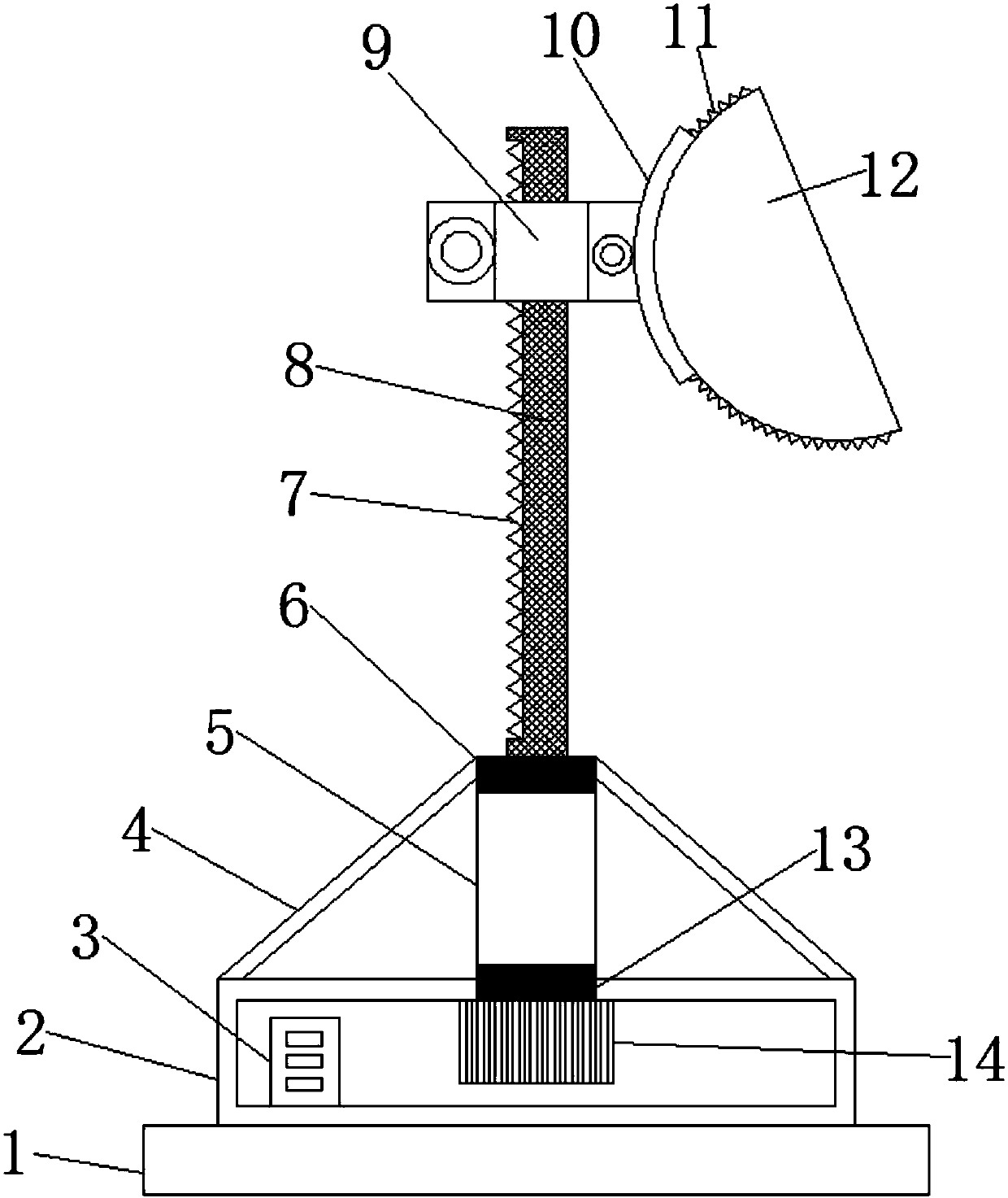
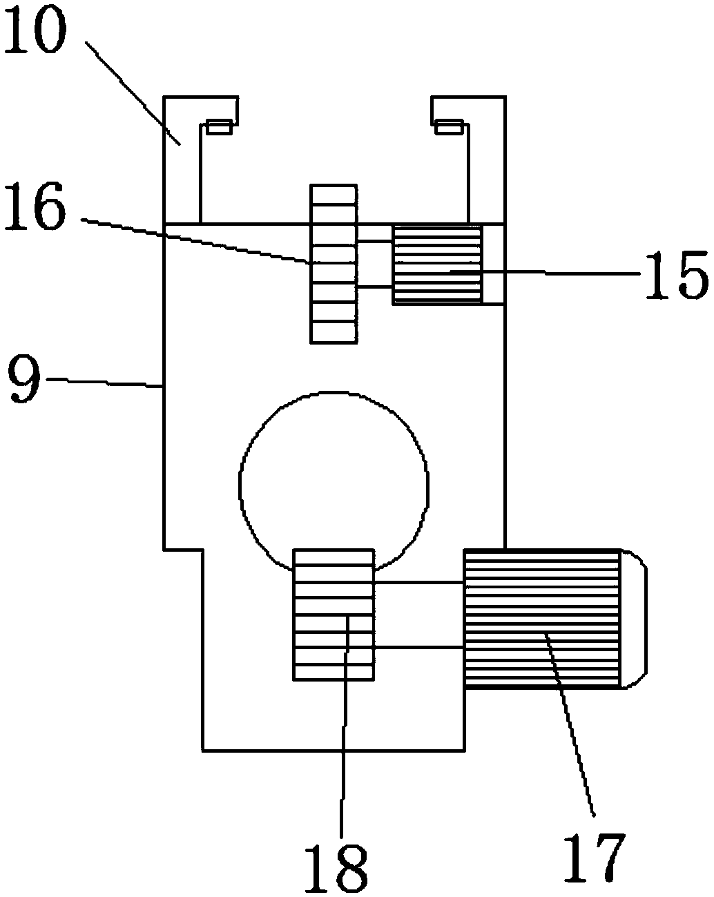
[0020] Reference Figure 1-2 , An antenna support for communication engineering, comprising a base 1, the top outer wall of the base 1 is fixed with a box 2 through bolts, and the bottom inner wall of the box 2 is fixed with a controller 3 through bolts, and the top outer wall of the box 2 has a central axis A circular opening is provided at the position, and the inner wall of the circular opening is fixed with a sleeve 5 by bolts, one side of the outer wall of the sleeve 5 is fixed with a support rod 4 by bolts, and the other end of the support rod 4 is fixed to the box 2 by bolts On the outer wall of the top end of the sleeve 5, the top a...


PUM


Abstract

The invention discloses an antenna bracket for communication engineering, which comprises a base. A box body is fixed on the top outer wall of the base through bolts, and a controller is fixed on thebottom inner wall of the box body through bolts. A circular opening is formed at the position of the central axis of the top outer wall of the box body, and a casing is fixed on the inner wall of thecircular opening through bolts. Support rods are fixed on the outer wall of one side of the casing through bolts, and the other end of each support rod is fixed on the top outer wall of the box body through a bolt. The top and bottom ends of the inner wall of the casing are sleeved with a first bearing and a second bearing respectively. By adding the casing, the antenna bracket can rotate while maintaining the stability of the antenna. By adding a connecting seat and two motors, the angle and height of the antenna can be adjusted automatically without manual adjustment, and the operation efficiency is greatly improved. The antenna bracket is reasonable in structure design, can carry out adjustment automatically, and makes the antenna easy to install and dismantle.

Description

Technical field [0001] The invention relates to the technical field of communication engineering, in particular to an antenna support for communication engineering. Background technique [0002] In antenna testing operations, it is generally necessary to adjust the height, azimuth, and pitch of the antenna to make the antenna receive the best signal; especially for satellite antennas, the ground antenna is required to be aligned with the satellite antenna on the satellite to ensure the signal Quality. According to the field test situation, the ground antenna needs to be erected to a certain height with an antenna bracket and adjusted to meet a certain azimuth and elevation angle. Therefore, the antenna support generally needs to have three ranges of height, azimuth and elevation angle. The degree of freedom is adjustable. Due to the complex structure and bulky size of the existing antenna support, it cannot be adapted to various test sites. In addition, due to the complex structu...

Claims


Application Information

Patent Timeline
IPC IPC(8): H01Q1/12H01Q3/02
Inventor 高焕云
Owner 高焕云
Learn More