Plane linear displacement drive device and control method thereof

A technology of linear displacement and driving device, which is applied in the control of plane linear displacement driving device and the field of plane linear displacement driving device, which can solve the problems of easy displacement deviation, inability to accurately control the displacement of the workpiece, and rough control of the displacement of the driving displacement device. , to achieve the effect of high-precision displacement control

Active Publication Date: 2019-06-28
CHANGCHUN INST OF OPTICS FINE MECHANICS & PHYSICS CHINESE ACAD OF SCI
View PDF8 Cites 3 Cited by
  • Summary
  • Abstract
  • Description
  • Claims
  • Application Information

AI Technical Summary

Problems solved by technology

At the same time, in order to realize the displacement output of large strokes, it is necessary to use driving displacement devices with different working principles, such as driving components such as oil cylinders or air cylinders. This type of driving displacement device has a large working stroke, which can meet the large stroke displacement of workpieces in the manufacturing process. demand, but the displacement control of this type of driving displacement device is relatively rough, it is impossible to accurately control the displacement of the workpiece, and it is prone to displacement deviation, which cannot be applied to the production and manufacture of high-precision engineering

Method used


Image

  • Plane linear displacement drive device and control method thereof
  • Plane linear displacement drive device and control method thereof
  • Plane linear displacement drive device and control method thereof

Examples


Embodiment Construction

[0030] The following will clearly and completely describe the technical solutions in the embodiments of the present invention with reference to the accompanying drawings in the embodiments of the present invention. Obviously, the described embodiments are only some, not all, embodiments of the present invention. Based on the embodiments of the present invention, all other embodiments obtained by persons of ordinary skill in the art without making creative efforts belong to the protection scope of the present invention.

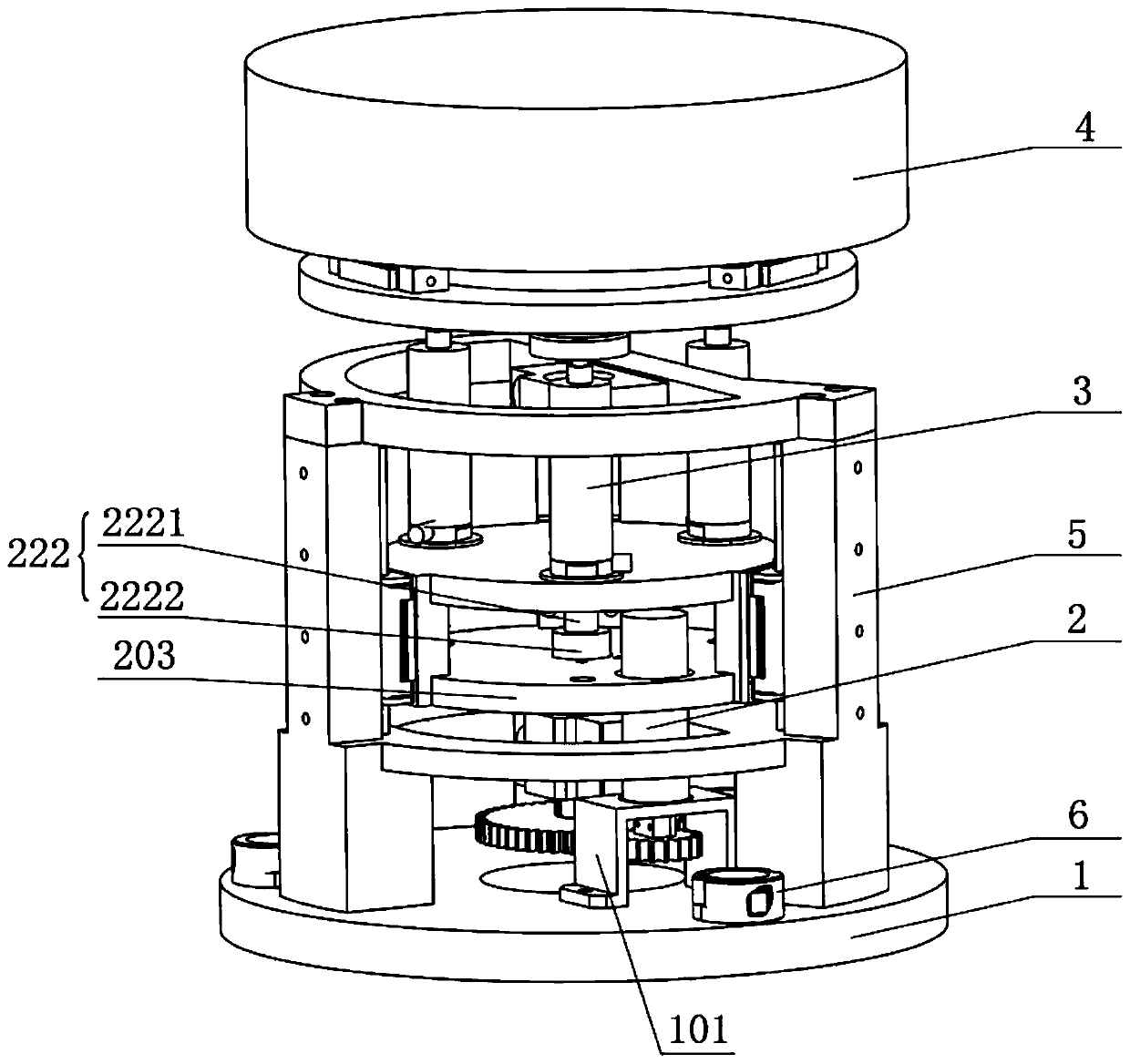
[0031] Please refer to figure 1 , figure 1 It is a schematic diagram of the overall structure of a specific embodiment provided by the present invention.

[0032] In a specific embodiment provided by the present invention, the planar linear displacement drive device mainly includes a support assembly 1 , a large-stroke drive mechanism 2 , a micro-displacement drive mechanism 3 and a stage 4 .

[0033] Wherein, the stage 4 is a component for mounting and carr...


PUM


Abstract

The invention discloses a plane linear displacement drive device which comprises a support assembly, a large-stroke drive mechanism arranged on the support assembly, a micrometric displacement drive mechanism connected with the output end of the large-stroke drive mechanism, and an objective table connected with the output end of the micrometric displacement drive mechanism. The micrometric displacement drive mechanism is a piezoelectric ceramic driver; and the large-stroke drive mechanism comprises a torque output device and a transmission assembly connected with the output end of the torqueoutput device and used for converting rotation movement into linear movement; and the movement directions of the transmission assembly and the piezoelectric ceramic driver are the axial direction of the objective table. According to the plane linear displacement drive device provided by the invention, the control requirements on large stroke and high-precision displacement of workpiece displacement during the production and manufacturing process of high-precision engineering can be simultaneously met, and the processing efficiency and the processing precision are improved. The invention further discloses a control method of the plane linear displacement drive device which has the beneficial effects as mentioned above.

Description

technical field [0001] The invention relates to the technical field of driving devices, in particular to a plane linear displacement driving device. The invention also relates to a control method of the plane linear displacement driving device. Background technique [0002] In recent years, with the continuous improvement of my country's industrial level, the demand for ultra-precision technology in various fields such as national defense industry, aerospace technology, bioengineering, microelectronics engineering, nanoscience and technology has become increasingly urgent, and the improvement of precision means that Product performance and quality have been greatly improved. Specifically, the manufacture and testing of micro-electromechanical systems, the production of large-scale integrated circuits, ultra-precision machining and precision measurement, etc., are inseparable from ultra-precision positioning technology, which has become one of the key technologies in the fiel...

Claims


Application Information

Patent Timeline
Patent Type & Authority Applications(China)
IPC IPC(8): B25H1/00B25H1/14
Inventor 李全超姚东徐钰蕾谭淞年
Owner CHANGCHUN INST OF OPTICS FINE MECHANICS & PHYSICS CHINESE ACAD OF SCI
Why Eureka
Try Eureka