Supercharge Your Innovation With Domain-Expert AI Agents!

Coupling service life testing equipment

A technology for testing equipment and couplings, applied in the field of coupling service life testing equipment, can solve problems such as the inability to meet a variety of coupling life tests, and achieve the effect of reducing test costs and reducing the number of purchases

Inactive Publication Date: 2020-10-16
CHONGQING COLLEGE OF ELECTRONICS ENG
View PDF9 Cites 0 Cited by
  • Summary
  • Abstract
  • Description
  • Claims
  • Application Information

AI Technical Summary

Problems solved by technology

[0005] In view of this, the present invention provides a coupling service life testing equipment to solve the technical problem that existing equipment cannot meet various coupling life testing

Method used


Image

  • Coupling service life testing equipment
  • Coupling service life testing equipment
  • Coupling service life testing equipment

Examples


Embodiment Construction

[0028] The present invention will be further described below in conjunction with embodiment and accompanying drawing.

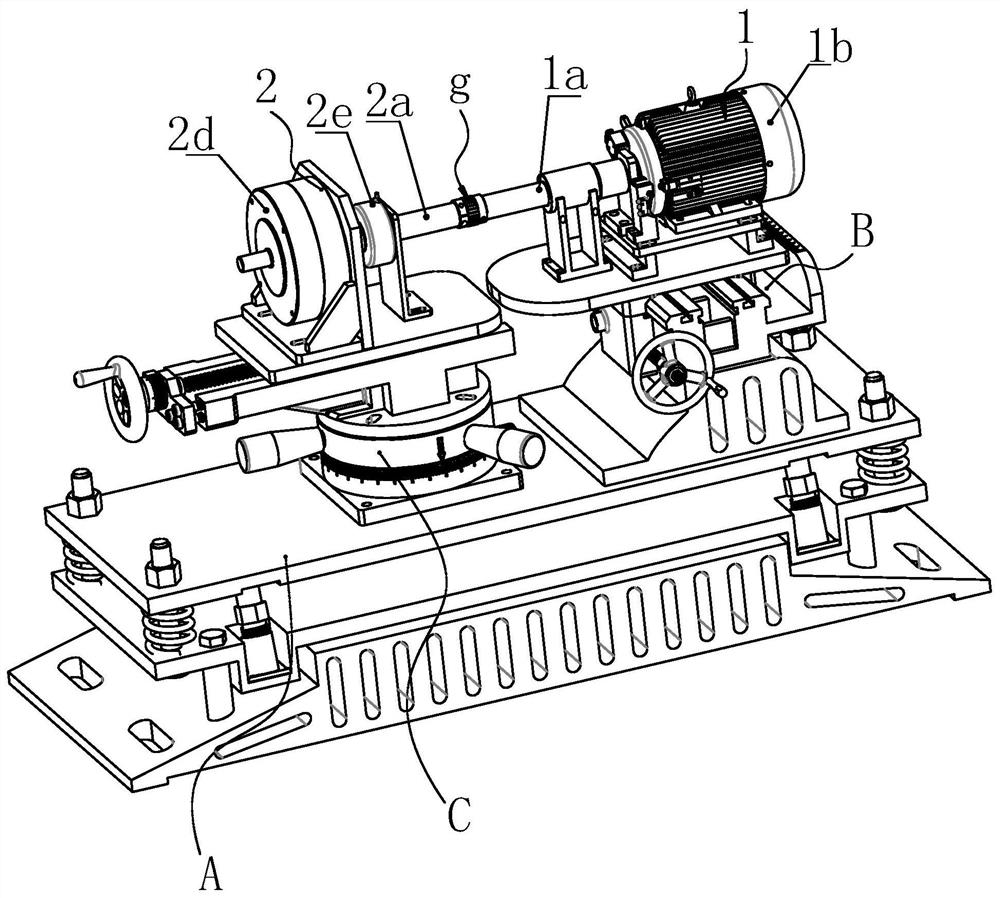
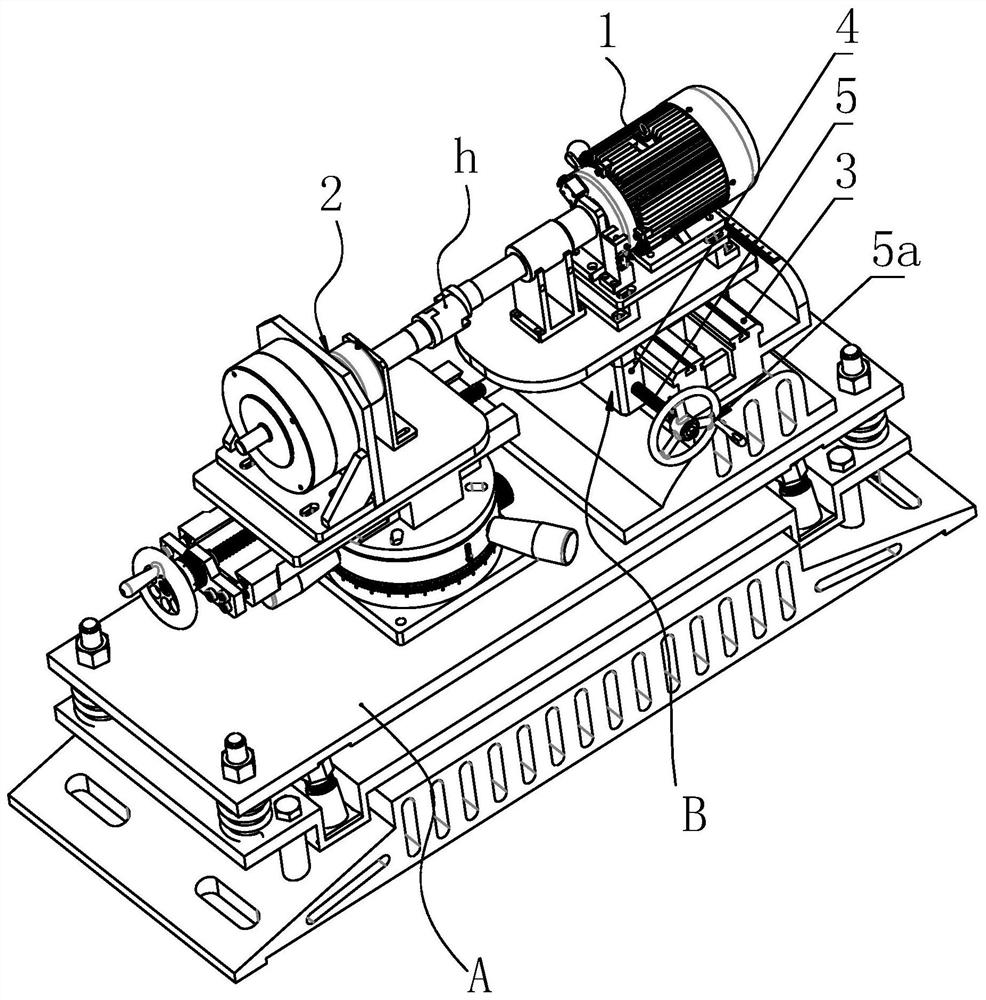
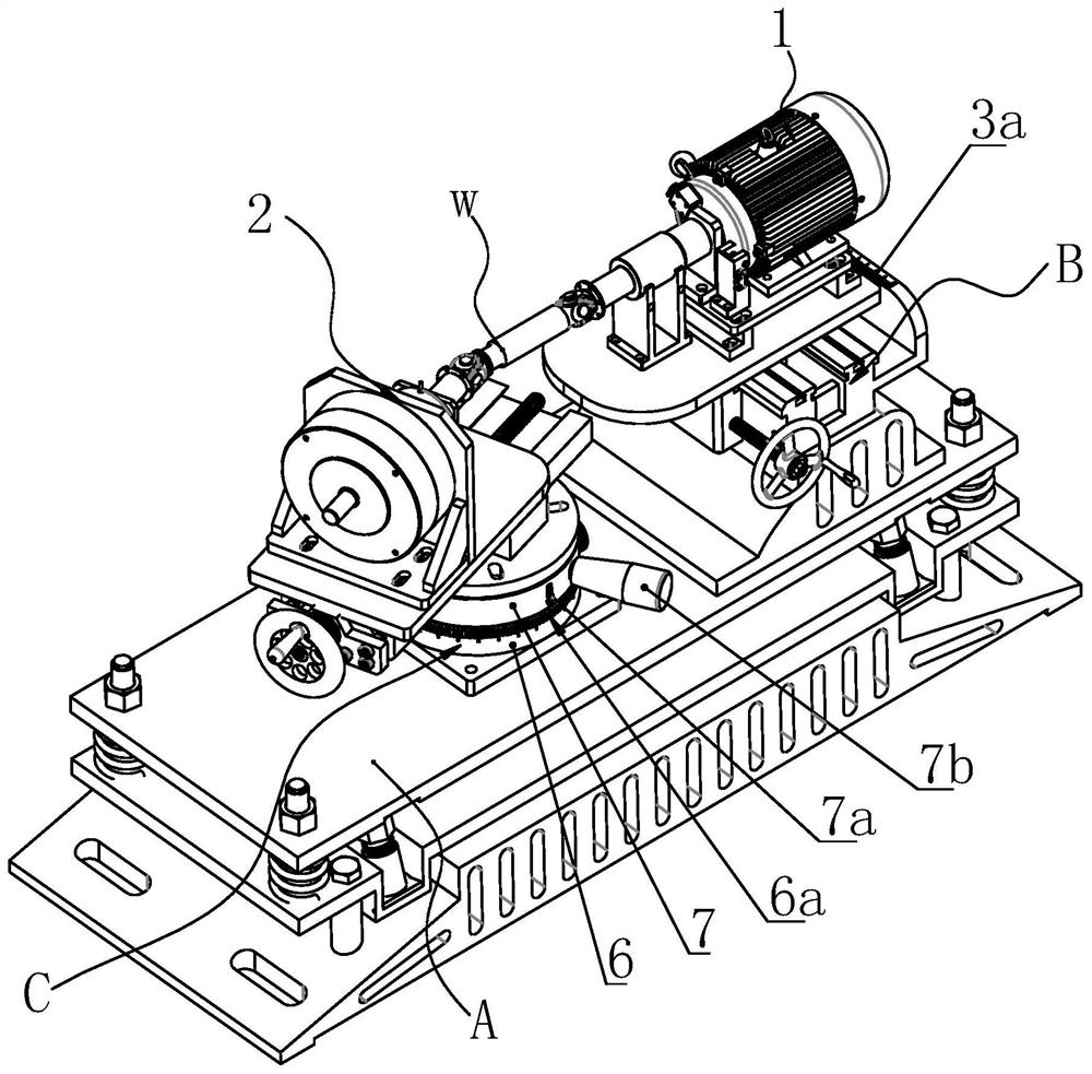
[0029] Such as Figures 1 to 3 As shown, a coupling service life testing equipment can be used to test the service life of three types of couplings. Its structure includes a device base A, a power end 1 with an output shaft 1a, and a load end with an input shaft 2a 2. The coupling to be tested is installed between the output shaft 1a and the input shaft 2a, the power end 1 provides output power, and the load end 2 provides torsion load. Wherein, the power end 1 is installed on the equipment base A through a lateral translation mechanism B, and the lateral translation mechanism B is used to adjust the radial deviation between the output shaft 1a and the input shaft 2a. The load end 2 is mounted on the equipment base A through a circular rotation mechanism C, which is used to adjust the angle between the output shaft 1a and the input shaft 2a.

[0030] Testin...


PUM


Abstract

The invention discloses a service life detecting device of a coupler. The device comprises a device base, a power end having an output shaft and a load end having an input shaft. The power end is mounted on the device base by a lateral translation mechanism; the lateral translation mechanism is used for adjusting the radial deviation between the output shaft and the input shaft. The load end is mounted on the device base by a circumferential rotation mechanism; and the circumferential rotation mechanism is used for adjusting the included angle between the output shaft and the input shaft. Thedetecting device has the beneficial effects that: the device can be used for testing the service life of the three types of couplers; the purchase quantity of the test equipment can be reduced; and the test cost is lowered substantially.

Description

technical field [0001] The invention belongs to the technical field of shaft coupling testing, and in particular relates to a coupling service life detection device. Background technique [0002] Couplings, also known as couplings, are mechanical components used to firmly connect the driving shaft and driven shaft in different mechanisms and transmit rotation and torque. Sometimes it is also used to connect shafts and other parts (such as gears, pulleys, etc.). The coupling is usually composed of two halves, which are fixedly installed on the ends of the two shafts facing each other with a key or a tight fit, and then the two halves are connected in some way. Some couplings also have the function of compensating the axial offset, radial offset and angular offset between the two shafts. [0003] Based on the above characteristics, according to different application scenarios, couplings have different classifications, among which the more common couplings are: rigid coupling...

Claims


Application Information

Patent Timeline
Patent Type & Authority Patents(China)
IPC IPC(8): G01M13/022G01M13/025G01M13/027
Inventor 张进春唐志君
Owner CHONGQING COLLEGE OF ELECTRONICS ENG
Features
  • R&D
  • Intellectual Property
  • Life Sciences
  • Materials
  • Tech Scout
  • Unparalleled Data Quality
  • Higher Quality Content
  • 60% Fewer Hallucinations
Learn More