Prepolarization coil current control system and control method for low-field nuclear magnetic resonance

A low-field nuclear magnetic resonance and control system technology, applied in current collectors, electric vehicles, electrical components, etc., can solve problems such as interference with imaging gradient fields, damage to IGBT switch tubes, and affecting imaging effects, and achieve the effect of ensuring safe use

Active Publication Date: 2020-12-29
NAT UNIV OF DEFENSE TECH +1
View PDF3 Cites 0 Cited by
  • Summary
  • Abstract
  • Description
  • Claims
  • Application Information

AI Technical Summary

Problems solved by technology

Usually, due to the self-inductance of the prepolarized coil (Bp coil), the current in the coil has a process of gradually weakening from large to small. ) is comparable in longitudinal relaxation time, it will interfere with the B0 field and imaging gradient field tested by the extremely low-field magnetic resonance imaging system, thereby affecting the imaging effect
[0004] At the same time, if figure 1 As shown, the drive circuit structure of the existing prepolarized coil is completely turned off after the prepolarized coil, the current passing through the prepolarized coil is the sum of the leakage currents of the two IGBT switch tubes, and the leakage current will also interfere with the subsequent magnetic field. The measurement of resonance affects the detection accuracy; and the negative prepolarization current cannot be generated in the existing structure. If the power supply is reversed, it will cause the electrolytic capacitor to charge the wrong polarity, which may cause explosion or damage the IGBT switch tube.

Method used


Image

  • Prepolarization coil current control system and control method for low-field nuclear magnetic resonance
  • Prepolarization coil current control system and control method for low-field nuclear magnetic resonance
  • Prepolarization coil current control system and control method for low-field nuclear magnetic resonance

Examples


Embodiment Construction

[0041]In order to enable those skilled in the art to better understand the technical solutions of the present invention, the present invention will be further described in detail below in conjunction with the accompanying drawings.

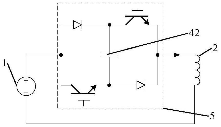
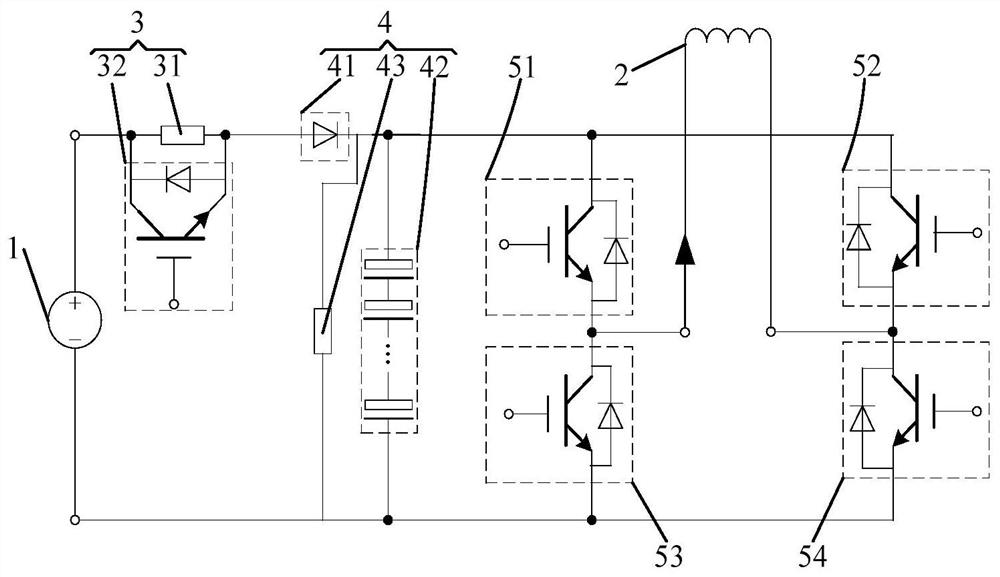
[0042] Such as figure 2 As shown, a prepolarized coil current control system for low-field nuclear magnetic resonance, including a power supply 1, a prepolarized coil 2, a charging protection circuit 3, a bootstrap boost circuit 4 and a bridge switch drive circuit, the The charging protection circuit 3 and the bootstrap boost circuit 4 are connected in series and form a loop with the power supply 1. The charging protection circuit 3 includes a charging resistor 31 and a fifth IGBT switch tube 32 connected in parallel. The voltage circuit 4 includes a power diode 41 and a capacitor bank 42 connected in series, the bridge switch drive circuit includes a first IGBT switch tube 51 and a third IGBT switch tube 53 connected in series and arranged at bo...


PUM


Abstract

The invention discloses a pre-polarization coil current control system for low-field nuclear paramagnetic resonance and a control method thereof. The control system comprises a power supply, a pre-polarization coil, a charging protection circuit, a bootstrap circuit and a bridge type symmetrical driving circuit, wherein the charging protection circuit and the bootstrap circuit are connected in series and form a loop with the power supply; the bridge type symmetrical driving circuit comprises four IGBT switch tubes connected in parallel with a capacitor; the four IGBT switch tubes form a symmetrical full-bridge structure so as to realize the switching-on and switching-off of current of the pre-polarization coil; and the pre-polarization coil is connected among the four IGBT switch tubes. When the bridge type symmetrical driving circuit is switched off, the self inductance current of the pre-polarization coil charges the capacitor group, so that the capacitor group generates the potential much higher than the power supply voltage and exerts the potential onto the pre-polarization coil, so that the current drop speed of the pre-polarization coil is continuously accelerated; and the fast switching-off of the current of the pre-polarization coil is realized.

Description

technical field [0001] The invention relates to the technical field of low-field nuclear magnetic resonance, in particular to a prepolarization coil current control system and control method for low-field nuclear magnetic resonance. Background technique [0002] Magnetic resonance imaging (MRI) has a good ability to distinguish soft tissues, and is widely used in biology, medicine and other fields, and has become a powerful means of clinical diagnosis. [0003] The current common high-field magnetic resonance imaging system (MRI) has been pursuing a higher main magnetic field strength B0 field strength, but this solution faces difficulties such as high cost and strict hardware requirements, and there are also problems that it is not suitable for special patients ; In contrast, the B0 field strength of the extremely low-field MRI system is low, and has the advantages of simple structure and low cost, and existing experiments have also shown that compared with high-field, diff...

Claims


Application Information

Patent Timeline
Patent Type & Authority Patents(China)
IPC IPC(8): H02J7/00H02J7/34H02M7/5387
CPCH02J7/0029H02J7/0034H02J7/345H02M7/5387
Inventor 周丹峰李杰董慧谭亦秋宋勐潇余佩倡
Owner NAT UNIV OF DEFENSE TECH
Why Eureka
Try Eureka