Bias suppression method and device

A magnetic bias suppression and magnetic bias technology, applied in the direction of output power conversion device, control/regulation system, DC power input conversion to DC power output, etc., can solve the problem of increasing circuit complexity, difficulty in selecting DC blocking capacitors, increasing conversion To avoid problems such as device size and cost, to avoid circuit complexity and size, increase circuit complexity and size, and suppress bias magnetism

Active Publication Date: 2021-08-17
ZTE CORP
View PDF6 Cites 0 Cited by
  • Summary
  • Abstract
  • Description
  • Claims
  • Application Information

AI Technical Summary

Problems solved by technology

Although this solution is simple, the addition of DC blocking capacitors increases the complexity of the circuit, and the selection of DC blocking capacitors for high current applications is very difficult, and at the same time increases the size and cost of the converter.

Method used


Image

  • Bias suppression method and device
  • Bias suppression method and device
  • Bias suppression method and device

Examples


Embodiment Construction

[0041] In order to make the purpose, technical solution and advantages of the present invention more clear, the embodiments of the present invention will be described in detail below in conjunction with the accompanying drawings. It should be noted that, in the case of no conflict, the embodiments in the present application and the features in the embodiments can be combined arbitrarily with each other.

[0042] The steps shown in the flowcharts of the figures may be performed in a computer system, such as a set of computer-executable instructions. Also, although a logical order is shown in the flowcharts, in some cases the steps shown or described may be performed in an order different from that shown or described herein.

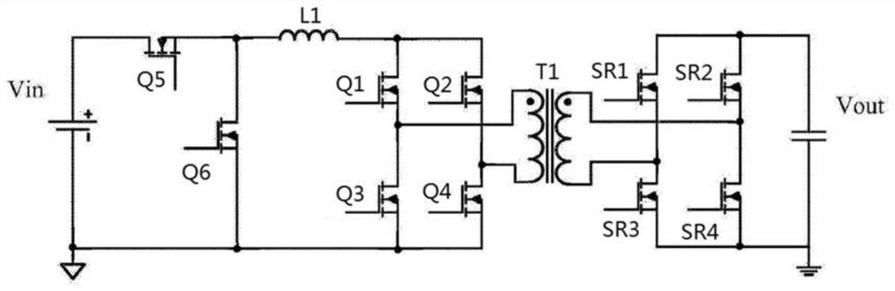
[0043] see figure 1 , figure 1 It is an isolated BUCK-BOOST (buck-boost) circuit. Among them, Vin is an input voltage source, and Q1, Q2, Q3, Q4, Q5, and Q6 are switching tubes. In this example, Q1, Q2, Q3, Q4, Q5, and Q6 are 100V MOSFETs (Metal-Oxide-...


PUM


Abstract

The embodiment of the present invention discloses a method and device for suppressing magnetic bias. The method includes: obtaining the bus voltage U1 when the transformer in the DC-DC converter is positively excited and the bus voltage U2 when it is negatively excited; The bus voltage U1 during positive excitation and the bus voltage U2 during negative excitation determine the bias compensation amount Δd1 during forward excitation of the transformer and the bias compensation amount Δd2 during negative excitation; when the transformer is positively excited The bias compensation amount Δd1 of the transformer is superimposed with the output duty cycle signal amount of the DC-DC converter loop, and is output to the switching tube excited in the positive direction, and the bias compensation amount Δd2 of the transformer in negative excitation is converted to DC-DC The loop output duty cycle signal is superimposed and output to the switching tube excited in the negative direction. The bias magnetism of the transformer can be effectively suppressed through the embodiments of the present invention.

Description

technical field [0001] The present application relates to the technical field of power electronics, in particular to a bias suppression method and device. Background technique [0002] In the field of power electronics technology, a DC-DC converter is a circuit that converts a DC power supply into another DC power supply with different output characteristics. In practical applications, due to the difference in the switching speed of the switching tube in the DC-DC converter, the difference in the delay of the driving signal, the difference in the pulse width of the driving signal, etc., long-term work will cause the transformer in the DC-DC converter to appear magnetically biased. [0003] In related technologies, a DC blocking capacitor is added to the topology of the circuit to eliminate transformer bias, and the DC blocking capacitor is connected in series with the transformer winding to block the DC component. Although this solution is simple, the addition of a DC block...

Claims


Application Information

Patent Timeline
Patent Type & Authority Patents(China)
IPC IPC(8): H02M3/335
CPCH02M3/33569H02M3/335H02M1/40
Inventor 胡永辉孟庆元卢至锋王俊杰
Owner ZTE CORP
Why Eureka
Try Eureka