optical lens

An optical lens and lens technology, which is applied in the field of optical lenses, can solve the problems of increased lens size and weight, unfavorable lens miniaturization, and increased cost, and achieve the effects of small aperture, high relative illuminance, and low cost

Active Publication Date: 2022-01-07
NINGBO SUNNY AUTOMOTIVE OPTECH
View PDF7 Cites 0 Cited by
  • Summary
  • Abstract
  • Description
  • Claims
  • Application Information

AI Technical Summary

Problems solved by technology

[0003] In order to increase the amount of incoming light, a lens with a small aperture is usually required. In order to improve the image quality, the number of lenses is usually increased, but the volume and weight of the lens will increase accordingly, which is not conducive to the miniaturization of the lens and will increase the cost.
[0004] At the same time, for some lenses for special applications, due to the influence of harsh environments, the image quality will deteriorate, so there is a high requirement for the ability of the lens to stabilize imaging within a large temperature range.

Method used


Image

  • optical lens
  • optical lens
  • optical lens

Examples


Embodiment 1

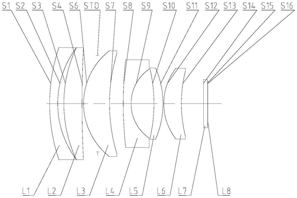
[0060] Refer to the following figure 1 An optical lens according to Embodiment 1 of the present application is described. figure 1 A schematic structural diagram of the optical lens according to Embodiment 1 of the present application is shown.

[0061] Such as figure 1 As shown, the optical lens sequentially includes a first lens L1 , a second lens L2 , a third lens L3 , a fourth lens L4 , a fifth lens L5 and a sixth lens L6 along the optical axis from the object side to the imaging side.

[0062] The first lens L1 is a meniscus lens with negative refractive power, the object side S1 is convex, and the image side S2 is concave.

[0063] The second lens L2 is a meniscus lens with positive refractive power, the object side S3 is convex, and the image side S4 is concave.

[0064] The third lens L3 is a meniscus lens with positive refractive power, the object side S6 is convex, and the image side S7 is concave.

[0065] The fourth lens L4 is a meniscus lens with negative refr...

Embodiment 2

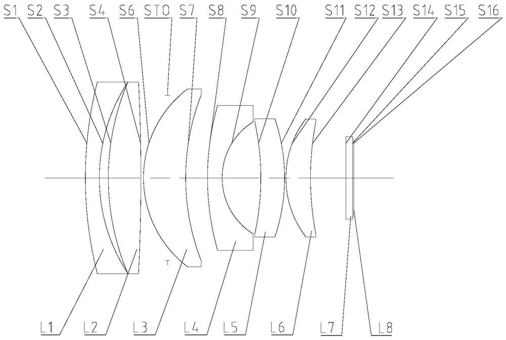
[0080] Refer to the following figure 2 An optical lens according to Embodiment 2 of the present application is described. In this embodiment and the following embodiments, for the sake of brevity, descriptions similar to those in Embodiment 1 will be omitted. figure 2 A schematic structural view of the optical lens according to Embodiment 2 of the present application is shown.

[0081] Such as figure 2 As shown, the optical lens sequentially includes a first lens L1 , a second lens L2 , a third lens L3 , a fourth lens L4 , a fifth lens L5 and a sixth lens L6 along the optical axis from the object side to the imaging side.

[0082] The first lens L1 is a meniscus lens with negative refractive power, the object side S1 is convex, and the image side S2 is concave.

[0083] The second lens L2 is a biconvex lens with positive refractive power, the object side S3 is convex, and the image side S4 is convex.

[0084] The third lens L3 is a meniscus lens with positive refractive...

Embodiment 3

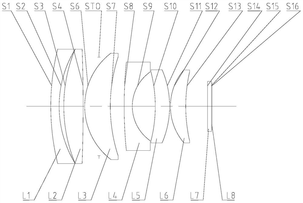
[0099] Refer to the following image 3 An optical lens according to Embodiment 3 of the present application is described. In this embodiment and the following embodiments, for the sake of brevity, descriptions similar to those in Embodiment 1 will be omitted. image 3 A schematic structural diagram of an optical lens according to Embodiment 3 of the present application is shown.

[0100] Such as image 3 As shown, the optical lens sequentially includes a first lens L1 , a second lens L2 , a third lens L3 , a fourth lens L4 , a fifth lens L5 and a sixth lens L6 along the optical axis from the object side to the imaging side.

[0101] The first lens L1 is a meniscus lens with negative refractive power, the object side S1 is convex, and the image side S2 is concave.

[0102] The second lens L2 is a biconvex lens with positive refractive power, the object side S3 is convex, and the image side S4 is convex.

[0103] The third lens L3 is a meniscus lens with positive refractive ...


PUM


Abstract

The present application discloses an optical lens, and the optical lens may sequentially include: a first lens, a second lens, a third lens, a fourth lens, a fifth lens and a sixth lens along the optical axis from the object side to the image side . Wherein, the first lens can have negative refractive power; the second lens, the third lens, the fifth lens and the sixth lens can have positive refractive power; and the fourth lens can have negative refractive power, and its object side is a convex surface, The image side is concave. According to the optical lens of the present application, effects such as miniaturization, small aperture, low cost, and high relative illuminance can be realized.

Description

technical field [0001] The present application relates to an optical lens, and more particularly, the present application relates to an optical lens including six lenses. Background technique [0002] At present, the application of optical lens is more and more extensive, and the requirement of lens miniaturization is also more and more prominent. [0003] In order to increase the amount of incoming light, a lens with a small aperture is usually required. In order to improve the image quality, the number of lenses is usually increased, but the volume and weight of the lens will increase accordingly, which is not conducive to the miniaturization of the lens and will increase the cost. [0004] At the same time, for some lenses for special applications, due to the influence of harsh environments, the image quality will deteriorate, so there is a high requirement for the ability of the lens to stabilize imaging within a large temperature range. [0005] Therefore, it is necess...

Claims


Application Information

Patent Timeline
Patent Type & Authority Patents(China)
IPC IPC(8): G02B13/00G02B13/18
CPCG02B13/00G02B13/18G02B13/0045
Inventor 徐超张俊明杨佳
Owner NINGBO SUNNY AUTOMOTIVE OPTECH
Why Eureka
Try Eureka