Coiler drum and coiling method capable of preventing steel coil from collapsing

A steel coil and machine coil technology, applied in the field of metallurgical steel rolling machinery, can solve the problems of high coiling tension, increase user costs, reduce product yield and other problems, increase secondary expansion force, improve sheet utilization, and ensure normal running effect

Active Publication Date: 2020-08-07
武汉钢铁有限公司
View PDF6 Cites 0 Cited by
  • Summary
  • Abstract
  • Description
  • Claims
  • Application Information

AI Technical Summary

Problems solved by technology

The collapse of the roll will affect the normal use of the machine or the user in the next process, and bring great losses to the manufacturer.
In order to correct the coil shape, a lot of manpower and material resources have to be spent, and sometimes the steel coil is even cut, which seriously disrupts the normal production organization, reduces the product yield, increases the user cost, and restricts the production line production efficiency
At present, in order to improve the collapse of steel coils, most cold-rolling manufacturers adopt the method of increasing the coiling tension and reducing the amount of oil applied to the strip. However, increasing the coiling tension can not only increase the radial pressure of the inner layer of the steel coil, but also Increase the tangential stress of the inner layer of the steel coil. When the tangential stress is greater than the static friction force between the layers of the steel coil, collapse will still occur. At the same time, the coiling tension is too large, and the strip steel in the inner layer of the steel coil will produce wrinkles, roll marks, etc. Core surface quality defects; reducing the amount of oil on the strip surface is also at the expense of reducing user quality requirements

Method used


Image

  • Coiler drum and coiling method capable of preventing steel coil from collapsing
  • Coiler drum and coiling method capable of preventing steel coil from collapsing
  • Coiler drum and coiling method capable of preventing steel coil from collapsing

Examples


Embodiment Construction

[0018] The present invention will be further described in detail below in conjunction with the accompanying drawings and specific embodiments.

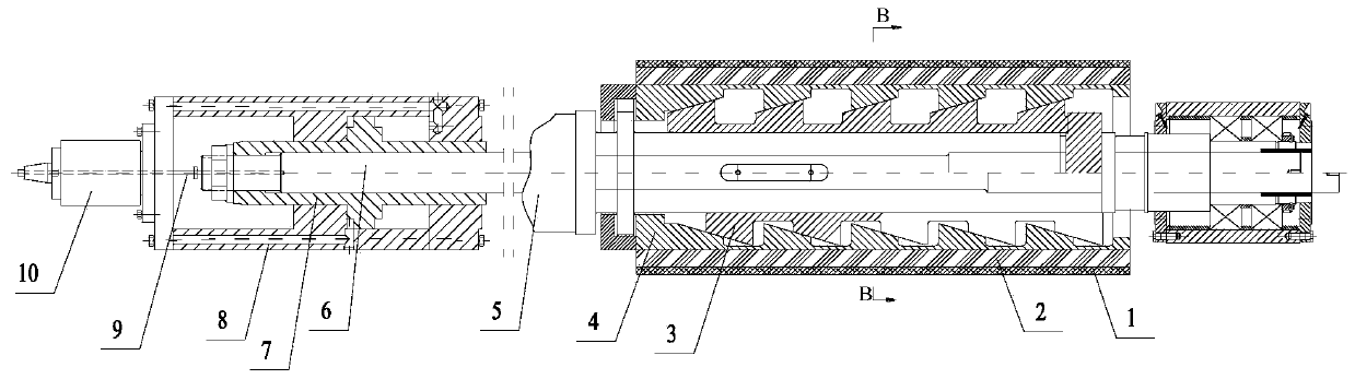
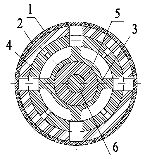
[0019] Such as figure 1 , figure 2 The coiler reel that can prevent the steel coil from collapsing shown in the figure includes a rubber sleeve 1, a plastic arc plate 2, a fan plate 4, a reel pyramid 3, a reel hollow main shaft 5, and an expander from the outside to the inside. The diameter cylinder 8, the rotary oiler 10 installed at one end of the expansion cylinder 8, the pull rod 6 fixedly connected to the piston 7 of the expansion cylinder 8 and connected to the piston 7 at one end, and the displacement sensor 9 installed at the end of the rotary oiler 10, The signal receiving end of the displacement sensor 9 passes through the rotary oiler 10 until the signal receiving end extends into the cavity of the pull rod 6. At the same time, the other end of the pull rod 6 is inserted into the reel hollow main shaft 5 and connected to ...


PUM

PropertyMeasurementUnit
thicknessaaaaaaaaaa

Abstract

The invention discloses a coiler coiling block capable of preventing steel coils from collapsing and a coiling method. The coiler coiling block comprises a rubber sleeve, a fan-shaped plate, a coilingblock pyramid body and a coiling block hollow main shaft, a diameter expanding cylinder, a rotary oil feeder installed at one end of the diameter expanding cylinder, a pull rod inserted into a pistonof the diameter expanding cylinder and fixedly connected with the piston and a displacement sensor installed at the tail end of the rotary oil feeder. The signal receiving end of the displacement sensor passes through the rotary oil feeder until the signal receiving end extends into a cavity of the pull rod, and the other end of the pull rod is inserted into the coiling block hollow main shaft and connected with the coiling block pyramid body through keys; and the thickness of rubber sleeve is about 15-20 mm. The coiler coiling block capable of preventing the steel coils from collapsing has afunction of secondary expansion and contraction and adopts the thin rubber sleeve; by increasing the additional tension of coiling, the coiling length of an additional tension area and the secondarydiameter expanding force of the coiling block are increased; and the stiffness of hard core layers of the steel coils can be improved under the combined action, so that the problem of collapsing of the steel coils is solved.

Description

technical field [0001] The invention relates to the technical field of metallurgical steel rolling machinery, in particular to a coiler drum and a coiling method capable of preventing steel coils from collapsing. Background technique [0002] After the steel coil is unloaded from the coiler of the production line, or in the process of hoisting, transportation, stacking, and storage, the steel coil will be deformed, and the inner hole of the steel coil will change from a perfect circle to an ellipse. This is the so-called Collapsing or flat rolling. The collapse of the roll will affect the normal use of the machine in the next process or the user, and bring great losses to the manufacturer. In order to correct the coil shape, a lot of manpower and material resources have to be spent, and sometimes the steel coil is even cut, which seriously disrupts the normal production organization, reduces the product yield, increases the user cost, and restricts the production line produ...

Claims


Application Information

Patent Timeline
Patent Type & Authority Patents(China)
IPC IPC(8): B21C47/30B21C47/10
CPCB21C47/10B21C47/30
Inventor 李良洪丁涛陈刚夏江涛方芳
Owner 武汉钢铁有限公司
Why Eureka
Try Eureka