Passive hydraulic train stopper

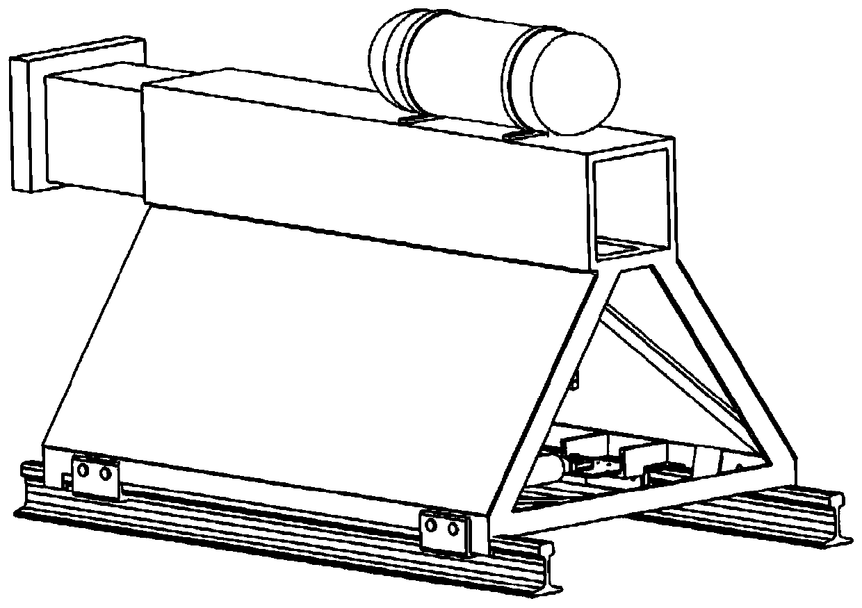
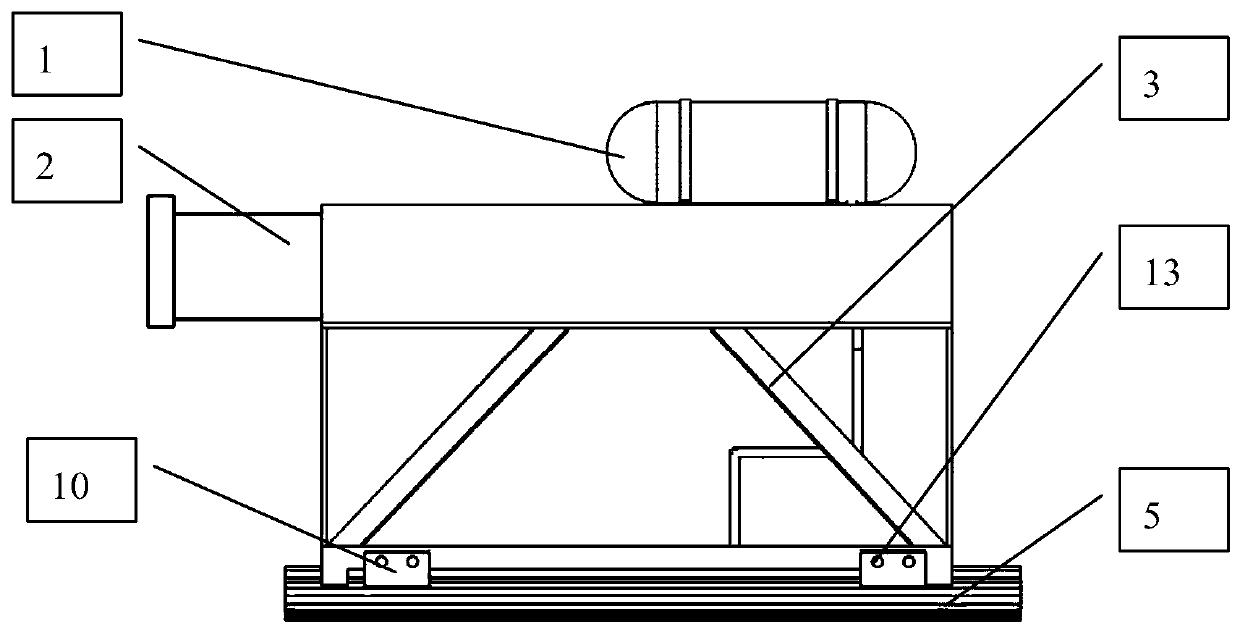
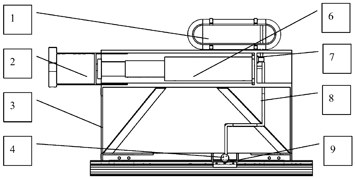
A car stopper, passive technology, applied in the direction of mandatory railway car stopper, railway car body parts, transportation and packaging, etc., it can solve the problems that the distance between dampers is difficult to arrange reasonably, the damping force of dampers is difficult to ensure consistency, and there are many dampers. , to achieve the effect of reducing the effective length of the occupied line, meeting the safety protection requirements of trains, and shortening the parking distance

Inactive Publication Date: 2019-07-23
DALIAN JIAOTONG UNIVERSITY
View PDF9 Cites 3 Cited by
  • Summary
  • Abstract
  • Description
  • Claims
  • Application Information

AI Technical Summary

Problems solved by technology

[0009] According to the existing sliding type car stop proposed above, there are: many dampers are installed, and the occupied line is long; the damping force is too large, which is easy to cause derailment; the damping force of a pair of dampers is difficult to e

Method used


Image

  • Passive hydraulic train stopper
  • Passive hydraulic train stopper
  • Passive hydraulic train stopper

Examples


Embodiment Construction

[0036] It should be noted that, in the case of no conflict, the embodiments of the present invention and the features in the embodiments can be combined with each other. The present invention will be described in detail below with reference to the accompanying drawings and examples.

[0037] In order to make the purpose, technical solutions and advantages of the embodiments of the present invention clearer, the technical solutions in the embodiments of the present invention will be clearly and completely described below in conjunction with the drawings in the embodiments of the present invention. Obviously, the described embodiments It is only some embodiments of the present invention, but not all embodiments. The following description of at least one exemplary embodiment is merely illustrative in nature and in no way taken as limiting the invention, its application or uses. Based on the embodiments of the present invention, all other embodiments obtained by persons of ordina...


PUM


Abstract

The invention relates to the technical field of rail traffic train or train set route end safety protection, in particular to a train set route end safety protection train stopper. The train set routeend safety protection train stopper comprises a contact, a main body frame, connecting buckle plates, a hydraulic system and a braking system; the bottoms of the two sides of the main body frame aremounted on a steel rail through the connecting buckle plates in a buckled mode; a hydraulic buffer of the hydraulic system and a two-stage hydraulic cylinder are fixed to the main body frame; a one-way overflow valve is mounted on the rear part of the two-stage hydraulic cylinder and communicates with the hydraulic buffer and a transverse thrust hydraulic cylinder through a hydraulic pipeline; thetransverse thrust hydraulic cylinder is connected with the braking system; the contact is mounted at the front end of the hydraulic buffer; a friction body frame bearing bracket of the braking systemis mounted on the inner side of the bottom of the main body frame; a friction body frame is arranged in the friction body frame bearing bracket and connected with the transverse thrust hydraulic cylinder through a force transmitting pin; and a friction body is mounted on the front part of the friction body frame, and friction force is generated through contacting of the friction body and the steel rail to brake the main body frame.

Description

technical field [0001] The invention relates to the technical field of safety protection at the end of rail transit trains or train lines, in particular to a safety protection car stopper at the end of train lines. Background technique [0002] The car stop is a safety protection facility installed at the end of the line, including a sliding car stop and a fixed car stop. The sliding car stop relies on sliding on the track to consume energy. Leave enough sliding distance; while the fixed stopper is just the opposite. The advantage is that it is placed at the end of the line and occupies less space on the track. The disadvantage is that it has poor impact resistance. Among them, the sliding type car stopper consumes the kinetic energy of the train through the friction between the damper and the track, and realizes the braking of the train, but the existing sliding type car stopper has the following defects: [0003] (1) Generally, the damper of the sliding car stop is set at...

Claims


Application Information

Patent Timeline
IPC IPC(8): B61K7/18
CPCB61K7/18
Inventor 刘爽王雷
Owner DALIAN JIAOTONG UNIVERSITY
Why Eureka
Try Eureka