Door hinge

A door hinge and hinge technology, which is applied in the field of connectors, can solve the problems of easy loosening and downward deviation, insufficient connection stability and unevenness, etc., and achieves the effect of maintaining smoothness, smooth switching and high stability.

Pending Publication Date: 2019-07-23
中山市超朗五金制品有限公司
View PDF6 Cites 3 Cited by
  • Summary
  • Abstract
  • Description
  • Claims
  • Application Information

AI Technical Summary

Problems solved by technology

[0003] The door hinge is a structure that connects the door with the wall, which can realize the free opening and closing of the door. Due to the improvement of people's living standards, the level of house decoration has also been greatly improved. Traditional wooden doors can no longer meet people's needs. Various metal and glass doors Used in large quantities, these doors are heavy. If the connection between the hinge and the door is not stable enough, the door will be affected by gravity after installation, and it is easy to loosen and shift downwards, resulting in unevenness between the inclined bottom of the door body and the ground or the door frame, making The door rotation is blocked and the switch is not smooth
[0004] Some door hinges use two sets of screws to fix the door with one push and one pull to maintain the stability of the connection. In this case, when the threads of the screws that generate tension wear and loosen, the screws that generate thrust cannot be fixed. The function of the door, on the contrary, will cause the door to loosen more seriously due to the thrust, and the connection with the door is not stable enough, and the door is easy to loosen and shift

Method used


Image

  • Door hinge
  • Door hinge
  • Door hinge

Examples


Embodiment Construction

[0023] It should be understood that the specific embodiments described here are only used to explain the present invention, not to limit the present invention.

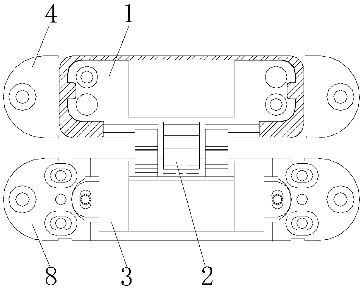
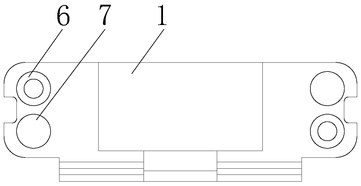
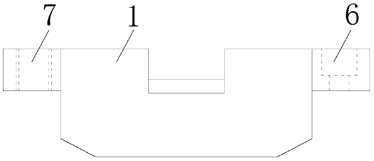
[0024] refer to Figure 1-7 , propose an embodiment of the present invention, a door hinge, including a first connecting plate 1 and a second connecting plate 3 hinged to the first connecting plate 1 through a hinge 2 and mounted on the wall, the first connecting plate 1 An installation seat 4 connected with the door is arranged on the outer end surface of the door. The mounting seat 4 is installed on the door, and the other side is connected with the first connecting plate 1. The mounting seat 4 can be embedded in the door or installed on the outer wall surface of the side wall of the door. When embedded in the door, the door is provided with the mounting seat 4 matching opening.

[0025] A groove 41 that can embed the first connecting plate 1 is provided on the side where the mounting base 4 is connected with the ...


PUM


Abstract

The invention discloses a door hinge, and relates to the technical field of connecting parts. The door hinge comprises a first connecting plate and a second connecting plate, wherein the second connecting plate and the first connecting plate are mounted on a wall in a hinged mode through a hinge; a mounting seat connected with a door is arranged on the outer end face of the first connecting plate,and a groove capable of allowing the first connecting plate to be embedded is formed in the face, connected with the first connecting plate, of the mounting seat; and first threaded holes and fixingbolts capable of rotating in the groove are arranged at the two ends of an inner cavity of the groove correspondingly, and first mounting holes and second threaded holes are formed in the two ends ofthe surface of the first connecting plate correspondingly. The door hinge adopts a plurality of sets of bolts to jointly act to generate bidirectional pulling force, the mounting seat is pulled to getclose to the first connecting plate mutually, when certain screws loose, the other bolts keep action to generate the puling force, the situation that connection of a door body gets loose due to sliding of one bolt is avoided, the stability of the connecting position is higher, the situation that the door body and the door hinge loose, consequently tilting is caused, and normal using of the door is affected is not prone to occurring, the smooth effect of door rotating is kept, and smooth opening and closing are kept.

Description

technical field [0001] The invention relates to the technical field of connectors, in particular to a door hinge. Background technique [0002] Door hinges, also known as hinges, are often composed of two folds, which are parts that connect two parts of an object and enable them to move. Ordinary door hinges are used for cabinet doors, windows, doors, etc. Among the existing doors and windows, door hinges are the most commonly used opening and closing structures. Using door hinges can facilitate the opening and closing of doors and windows. [0003] The door hinge is a structure that connects the door with the wall, which can realize the free opening and closing of the door. Due to the improvement of people's living standards, the level of house decoration has also been greatly improved. Traditional wooden doors can no longer meet people's needs. Various metal and glass doors Used in large quantities, these doors are heavy. If the connection between the hinge and the door i...

Claims


Application Information

Patent Timeline
Patent Type & Authority Applications(China)
IPC IPC(8): E05D5/02
CPCE05D5/02
Inventor 刘毅锋黄涛
Owner 中山市超朗五金制品有限公司
Why Eureka
Try Eureka