Impedance identification method of power grid of grid-connected inverter based on high-frequency signal injection

A high-frequency signal and grid impedance technology, which is applied in the direction of measuring resistance/reactance/impedance, instruments, measuring electrical variables, etc., can solve the problems of ineffective injection, low grid impedance identification accuracy, and high-frequency signals without considering DC bias, etc. question

Active Publication Date: 2019-07-23
ZHENGZHOU UNIVERSITY OF LIGHT INDUSTRY +1
View PDF16 Cites 5 Cited by
  • Summary
  • Abstract
  • Description
  • Claims
  • Application Information

AI Technical Summary

Problems solved by technology

[0005] Aiming at the technical problem that the existing grid impedance identification method cannot inject effective high-frequency signals and does not consider the introduction of DC bias into the voltage and current sampling channels, resulting in low identification accuracy of grid impedance, the present invention proposes a high-frequency based The grid-connected inverter grid impedance identification method based on signal injection, firstly, inject three-phase high-frequency voltage signals into the three-phase modulation voltage signal, so that the high-frequency signal can be realized without changing the original proportional-integral controller parameters of the current loop. injection

Method used


Image

  • Impedance identification method of power grid of grid-connected inverter based on high-frequency signal injection
  • Impedance identification method of power grid of grid-connected inverter based on high-frequency signal injection
  • Impedance identification method of power grid of grid-connected inverter based on high-frequency signal injection

Examples


Embodiment Construction

[0058] The following will clearly and completely describe the technical solutions in the embodiments of the present invention with reference to the accompanying drawings in the embodiments of the present invention. Obviously, the described embodiments are only some, not all, embodiments of the present invention. Based on the embodiments of the present invention, all other embodiments obtained by persons of ordinary skill in the art without making creative efforts belong to the protection scope of the present invention.

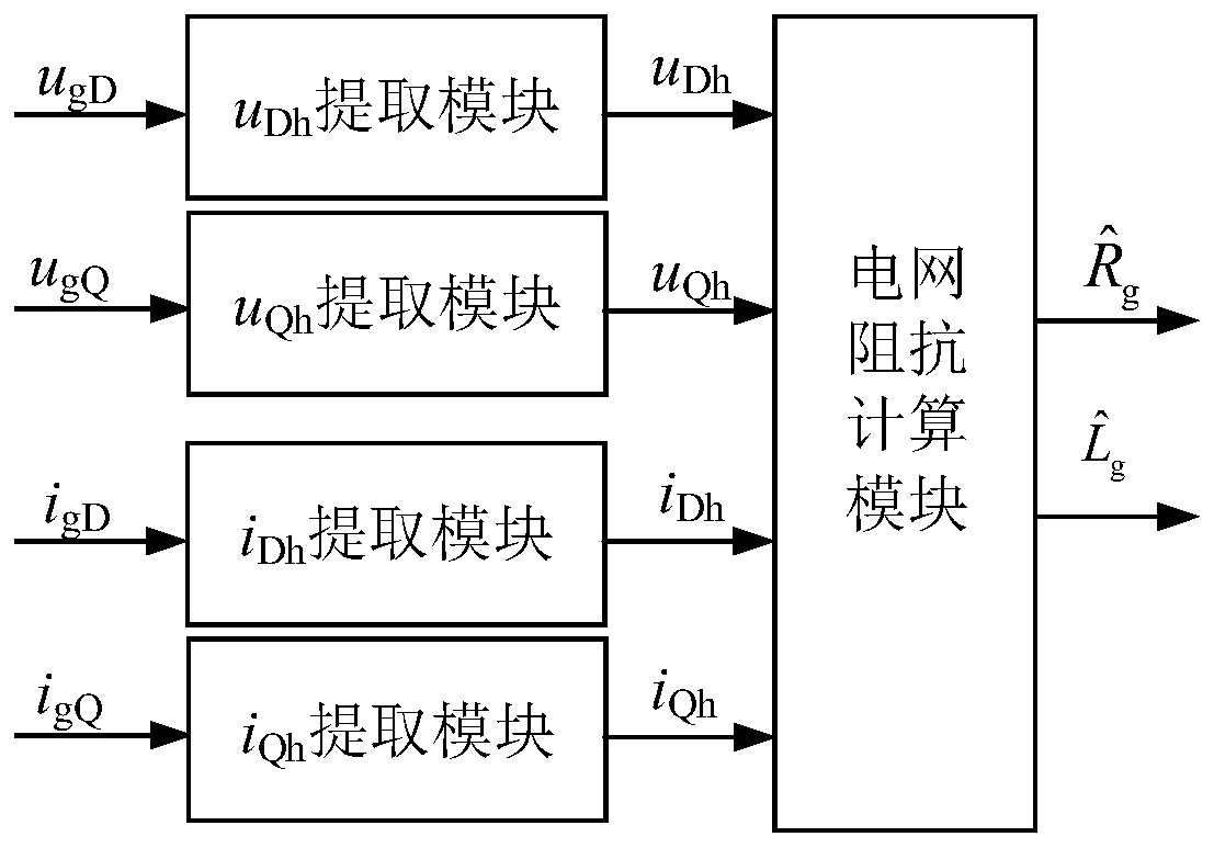
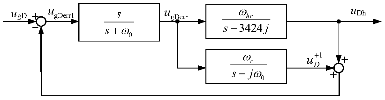
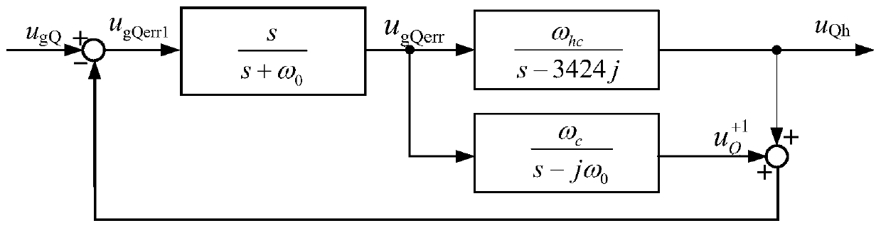
[0059] Such as figure 1 and Figure 6 As shown, the present invention proposes a grid-connected inverter grid impedance identification method based on high-frequency signal injection. First, the voltage sensor and current sensor are used to obtain the voltage of the grid-connected inverter and the current of the bridge arm side, and the ratio The integrator transforms the voltage and the current on the bridge arm side to obtain the modulated voltage signal; t...


PUM


Abstract

The invention provides an impedance identification method of a power grid of a grid-connected inverter based on high-frequency signal injection. The method comprises the following steps: firstly, respectively measuring the voltage and bridge arm side current of the grid-connected inverter by using a voltage sensor and a current sensor, and converting the voltage and the bridge arm side current through a proportional integral controller to obtain a modulated voltage signal; then, injecting a three-phase high-frequency voltage signal into the modulated voltage signal to update the voltage of thegrid-connected inverter, measuring the power grid side current of the grid-connected inverter by using the current sensor, and respectively substituting the updated voltage and the power grid side current into a voltage extraction module and a current extraction module; and finally, extracting a high-frequency voltage signal and a high-frequency current signal of a grid of the grid-connected inverter by using an improved complex number filter so as to solve an impedance value of the power grid in real time. According to the impedance identification method provided by the invention, the three-phase high-frequency voltage signal is directly superimposed on the modulated voltage signal, thereby ensuring the effective injection of the high-frequency signal and being able to improve the signal-to-noise ratio of the power grid, so that the impedance identification accuracy of the power grid is improved.

Description

technical field [0001] The invention relates to the technical field of power electronics, in particular to a grid-connected inverter grid impedance identification method based on high-frequency signal injection. Background technique [0002] In recent years, with the rapid expansion of the installation scale of new energy grid-connected inverters, more and more power grids have shown the characteristics of "weak grids", and their impedance is also increasing, which affects the stability of grid-connected inverters. Running has had a huge impact. In order to improve the operation stability of the grid-connected inverter under the weak grid, it is necessary to identify the grid impedance in real time, and adjust the operation mode of the grid-connected inverter in real time according to the grid impedance value. Commonly used grid impedance identification methods mainly include passive methods and active methods. The passive method calculates the grid impedance by detecting ...

Claims


Application Information

Patent Timeline
Patent Type & Authority Applications(China)
IPC IPC(8): G01R27/02
CPCG01R27/02
Inventor 郭磊磊金楠秦世耀王瑞明代林旺曹玲芝李琰琰武洁吴振军窦智峰
Owner ZHENGZHOU UNIVERSITY OF LIGHT INDUSTRY
Why Eureka
Try Eureka