
Automatic debugging equipment for filter

An automatic debugging and filter technology, applied in the field of filters, can solve problems such as low filter debugging efficiency, and achieve the effect of improving debugging efficiency

Pending Publication Date: 2019-07-26
三亚市以恒实业有限公司
View PDF0 Cites 6 Cited by
  • Summary
  • Abstract
  • Description
  • Claims
  • Application Information

AI Technical Summary

Problems solved by technology

[0004] In order to overcome the shortcomings and deficiencies in the prior art, the purpose of the present invention is to provide a filter automatic debugging equipment, which solves the problem of low filter debugging efficiency

Method used


Image

  • Automatic debugging equipment for filter
  • Automatic debugging equipment for filter
  • Automatic debugging equipment for filter

Examples


Embodiment Construction

[0053] Embodiments of the present invention are described below through specific examples, and those skilled in the art can easily understand other advantages and effects of the present invention from the content disclosed in this specification. The present invention can also be implemented or applied through other different specific implementation modes, and various modifications or changes can be made to the details in this specification based on different viewpoints and applications without departing from the spirit of the present invention.

[0054] It should be noted that the structures shown in the drawings of this specification are only used to cooperate with the content disclosed in the specification for the understanding and reading of those who are familiar with this technology, and are not used to limit the conditions for the implementation of the present invention. Therefore, It has no technical substantive meaning, and any modification or adjustment of the structur...


PUM


Abstract

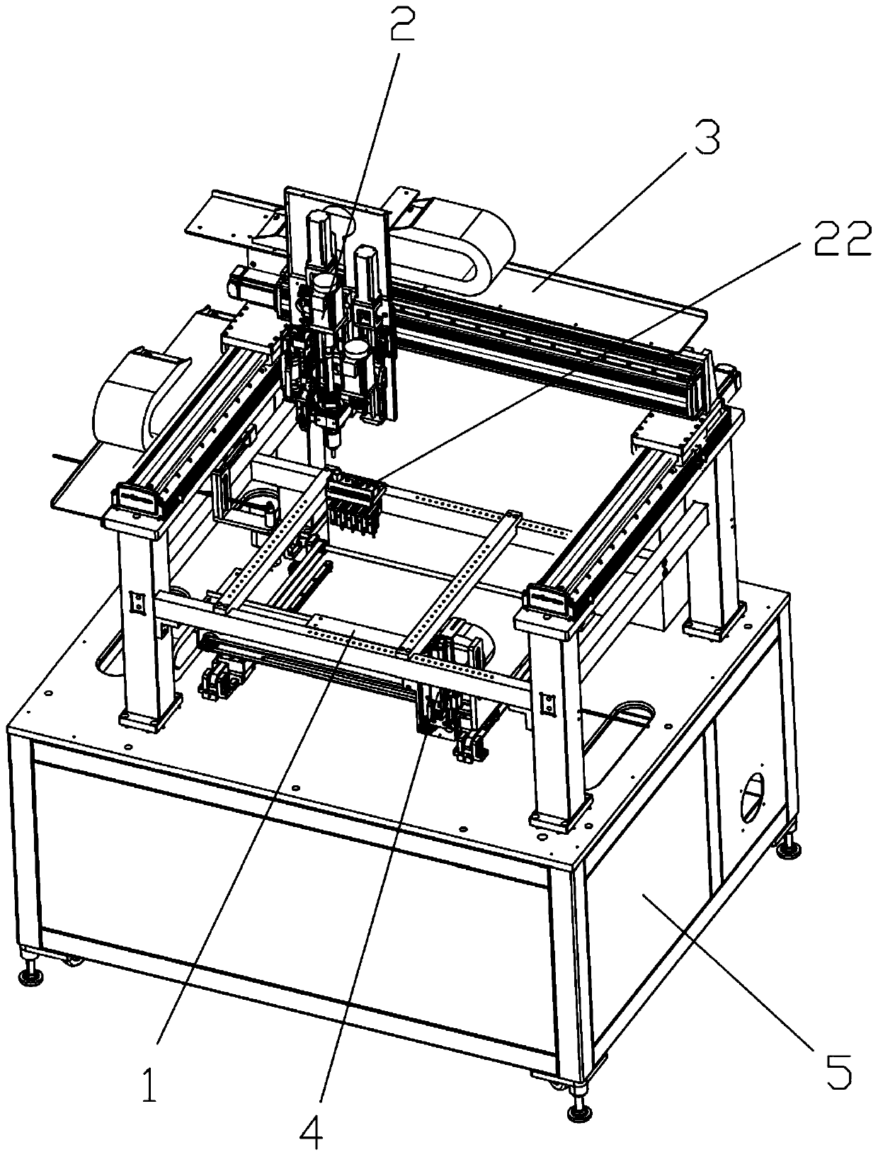
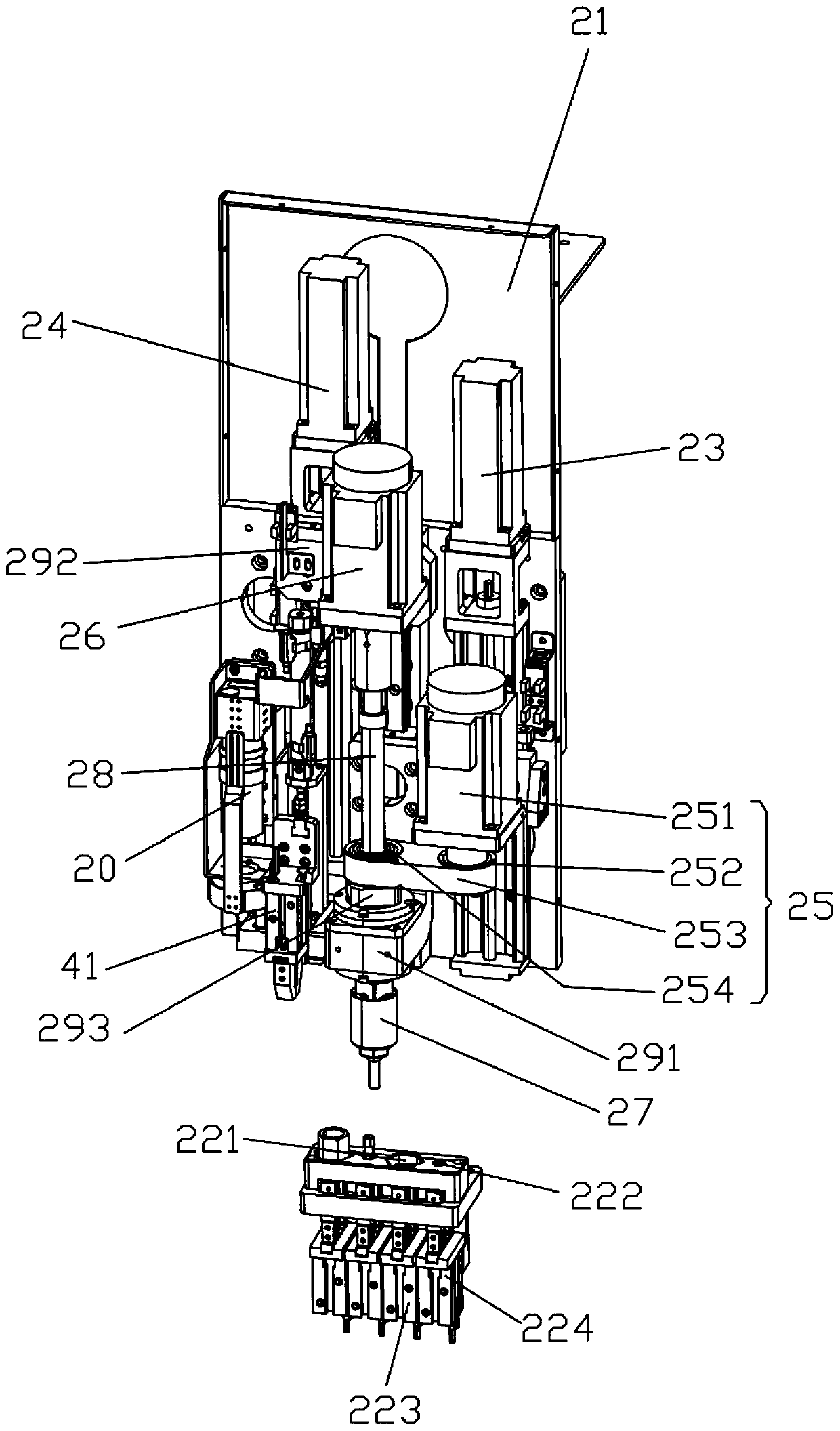
The invention relates to the technical field of filters, in particular to automatic debugging equipment for a filter. The automatic debugging equipment for the filter comprises a rack, and a placementtable, a debugging mechanism and a debugging translation driving mechanism which are arranged on the rack, wherein the placement table is used for placing a filter to be debugged; the debugging mechanism is used for automatically debugging the filter placed on the placing table; and the debugging translation driving mechanism is used for driving the debugging mechanism to carry out translation. According to the automatic debugging equipment for the filter, a problem of low debugging efficiency of the filter is solved.

Description

technical field [0001] The invention relates to the technical field of filters, in particular to a filter automatic debugging device. Background technique [0002] The power filter is a filter circuit composed of capacitors, inductors and resistors. The filter can effectively filter the frequency point of a specific frequency in the power line or frequencies other than this frequency point to obtain a power signal of a specific frequency or eliminate a power signal of a specific frequency. [0003] In the mobile network communication technology, the filter is a very important part of the base station. It is necessary for the filter to adjust the signals of different bands to a suitable frequency before the base station can transmit mobile communication signals. Under normal circumstances, the adjustment of the frequency of the filter signal is performed manually, which is inefficient. Contents of the invention [0004] In order to overcome the shortcomings and deficienci...

Claims


Application Information

Patent Timeline
Patent Type & Authority Applications(China)
IPC IPC(8): G01R1/04G01R31/00
CPCG01R1/04G01R31/00
Inventor 吴水鱼
Owner 三亚市以恒实业有限公司
Learn More