Polishing equipment

A kind of optical equipment and equipment technology, applied in the direction of metal processing equipment, used abrasive processing devices, abrasives, etc., can solve the problems of affecting the glass yield, slow production cycle, and low yield rate of 3D glass, so as to reduce the damage wait time The probability of sweeping the product and the effect of improving the yield

Pending Publication Date: 2019-07-30
QINGYUAN CSG NEW ENERGY SAVING MATERIALS CO LTD +1
View PDF5 Cites 0 Cited by
  • Summary
  • Abstract
  • Description
  • Claims
  • Application Information

AI Technical Summary

Problems solved by technology

However, both of these two sweeping processes directly contact the glass surface, which is a contact-heavy pressure sweeping method, which has the risk of damaging the glass and affects the yield of the glass.
[0003] Moreover, as more and more electronic products such as mobile phones use 3D and other special-shaped glass, when producing 3D glass, one of the above two light-sweeping processes is usually used to sweep the flat glass first, and then heat the flat glass. Bending into 3D glass, after forming 3D glass, no more sweeping, and the surface of 3D glass formed by hot bending will have more defects, such as embossing, dirt, white spots, orange lines, tin marks, etc., resulting in 3D The yield of glass is extremely low
[0004] Some manufacturers of light-sweeping equipment began to design the lower-sweeping mold in the above-mentioned second light-sweeping process as a curved surface structure to facilitate the light-sweeping of 3D glass. The yield rate of 3D glass is still very low, and a set of upper brush and lower sweeping mold can only match one kind of 3D glass product, and 3D glass products with different structures need to formulate corresponding upper brush and lower sweeping mold, processing High cost and slow production cycle

Method used


Image

  • Polishing equipment
  • Polishing equipment
  • Polishing equipment

Examples


Embodiment Construction

[0022] The light-sweeping device will be further described below in conjunction with the accompanying drawings and specific embodiments.

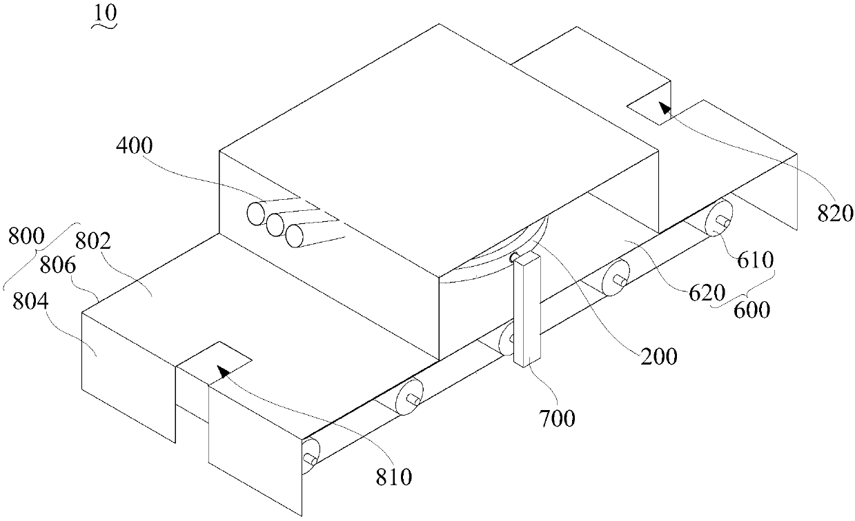
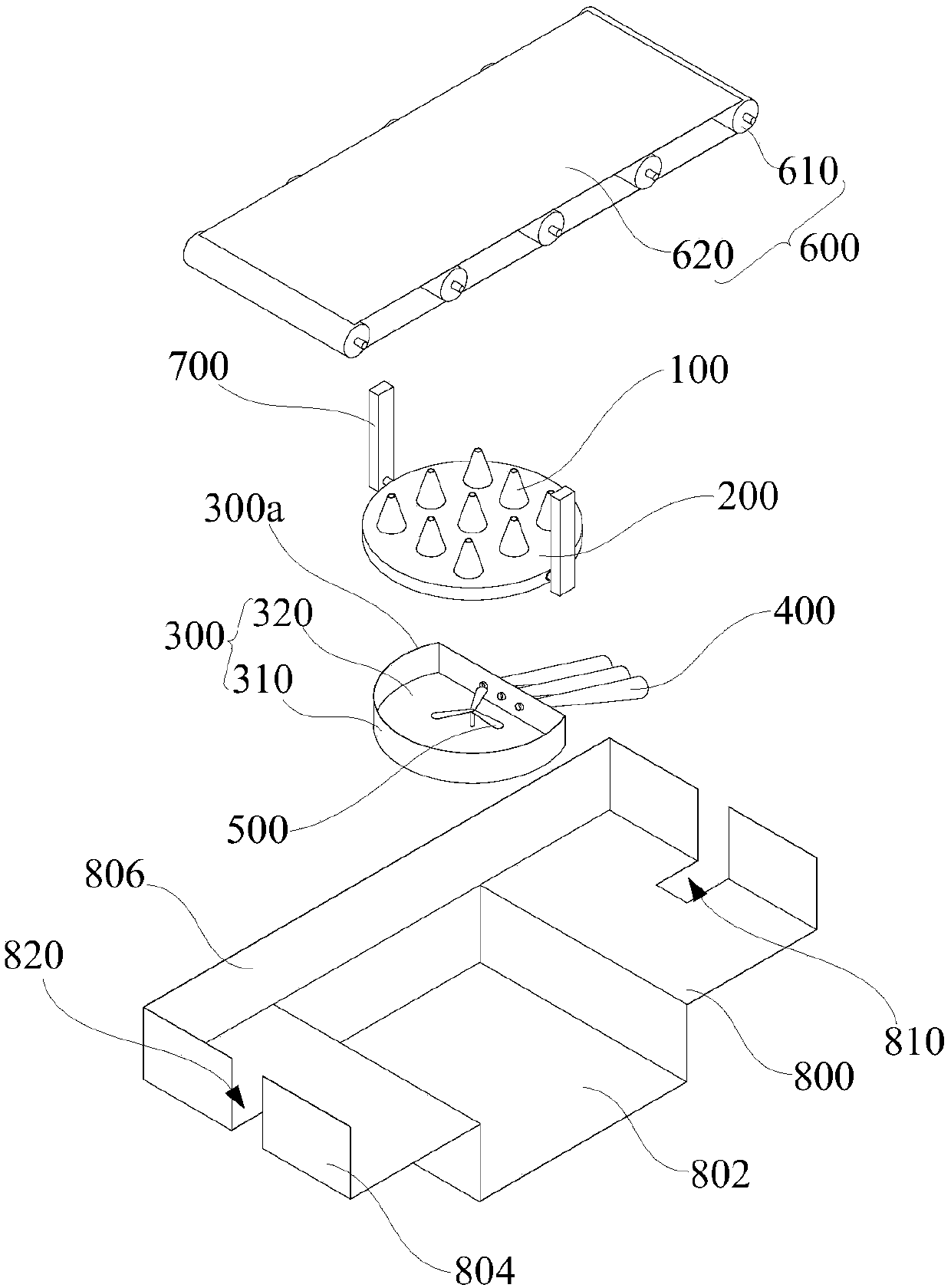
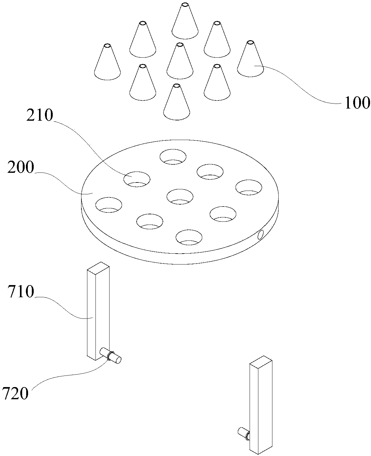
[0023] Such as figure 1 and figure 2 As shown, the sweeping device 10 according to an embodiment of the present invention includes a high-pressure spray gun 100 , a rotating disk 200 , an abrasive shell 300 , a feeding tube 400 , a homogeneous mixer 500 , a carrying assembly 600 , a rotating support frame 700 and a housing 800 .

[0024] The high-pressure spray gun 100 is used to be spaced apart from the product to be cleaned, and the high-pressure spray gun 100 can spray abrasives onto the product to be cleaned to sweep the product to be cleaned, so that the above-mentioned light-sweeping device 10 is non-destructive when cleaning the product. Heavy pressure-non-contact sweeping can effectively reduce the probability of damaging the product to be swept and improve the yield of the product to be swept. Moreover, the high-pressure spray g...


PUM


Abstract

The invention relates to polishing equipment. The polishing equipment comprises a high-pressure spray gun, the high-pressure spray gun is used for being arranged spaced from a to-be-polished product,the high-pressure spray gun can spray an abrasive to the to-be-polished product so as to polish the to-be-polished product, and the high-pressure spray gun can rotate so that the high-pressure spray gun can be aligned with different areas of the to-be-polished product. In the polishing equipment, the high-pressure spray gun is used for being arranged spaced from the to-be-polished product, the high-pressure spray gun can spray the abrasive to the to-be-polished product so as to polish the to-be-polished product, so that when the polishing equipment polishes the product, non-heavy pressure andnon-contact polishing can be realized, then the probability of damaging the to-be-polished product is effectively reduced, and the finished product rate of the to-be-polished product is improved. Moreover, the high-pressure spray gun can rotate so that the high-pressure spray gun can be aligned with different areas of the to-be-polished product, thus the polishing equipment can polish the to-be-polished products with 3D and other special shapes, and the polishing equipment is not influenced by the size and shape of the to-be-polished product.

Description

technical field [0001] The invention relates to the technical field of glass processing, in particular to a light sweeping device. Background technique [0002] The traditional glass sweeping (polishing) process mainly includes two kinds, the first is to realize the sweeping of the glass surface through the grinding of the upper and lower grinding discs; the second is to use the upper brush and the lower sweeping mold (used to fix the glass) ) to achieve the sweeping of the glass surface. However, both of these two sweeping processes directly contact the glass surface, which is a contact-heavy pressure sweeping method, which has the risk of damaging the glass and affects the yield of the glass. [0003] Moreover, as more and more electronic products such as mobile phones use 3D and other special-shaped glass, when producing 3D glass, one of the above two light-sweeping processes is usually used to sweep the flat glass first, and then heat the flat glass. Bending into 3D gl...

Claims


Application Information

Patent Timeline
Patent Type & Authority Applications(China)
IPC IPC(8): B24C3/32B24C9/00
CPCB24C3/32B24C9/00
Inventor 樊颖魏猛周翔磊龚锋杰刘红刚李彦彬
Owner QINGYUAN CSG NEW ENERGY SAVING MATERIALS CO LTD
Why Eureka
Try Eureka