Stent used for valve-in-valve intervention

A technology of strut and inflow end, applied in the field of interventional valve-in-valve and interventional pulmonary valve, can solve the problems of uncertain durability, failure, damage or calcification of biological valve, achieve reasonable fixation, good adhesion, avoid valve The effect of leaking

Pending Publication Date: 2019-08-02
BEIJING BALANCE MEDICAL
View PDF5 Cites 1 Cited by
  • Summary
  • Abstract
  • Description
  • Claims
  • Application Information

AI Technical Summary

Problems solved by technology

In view of the fact that all kinds of artificial bioprosthetic valves still face the uncertainty of durability, it is inevitable that some patients will experience damage or calcification of the bioprosthetic valve after surgery, resulting in failure

Method used


Image

  • Stent used for valve-in-valve intervention
  • Stent used for valve-in-valve intervention
  • Stent used for valve-in-valve intervention

Examples


Embodiment Construction

[0019] The following specific examples are used to illustrate specific implementation methods. It should be understood that the specific examples described here are only used to explain the present invention, and are not intended to limit the present invention.

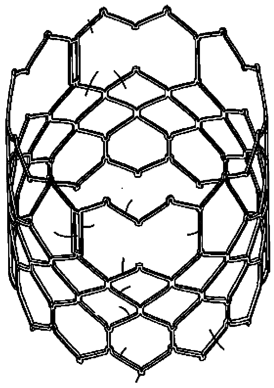
[0020] Interventional valve-in-valve is usually used in previously surgically implanted or intervened failed bioprosthetic heart valves (including implanted or intervened bioprosthetic valves in four valve positions) to achieve reintervention of heart valves. The existing stent structures for interventional valve-in-valve are as follows: figure 1 shown.

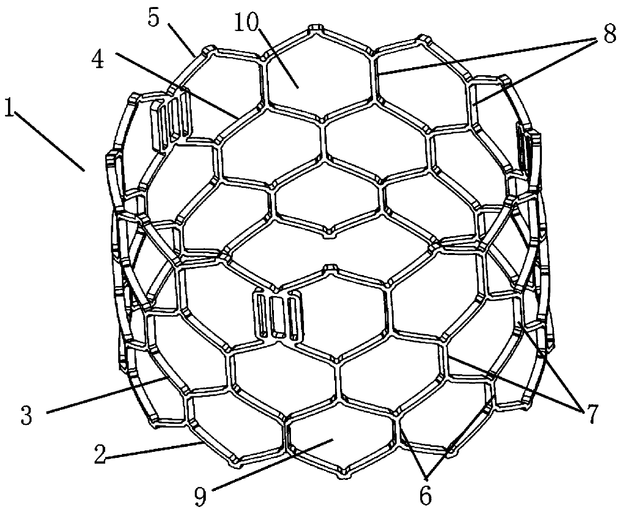
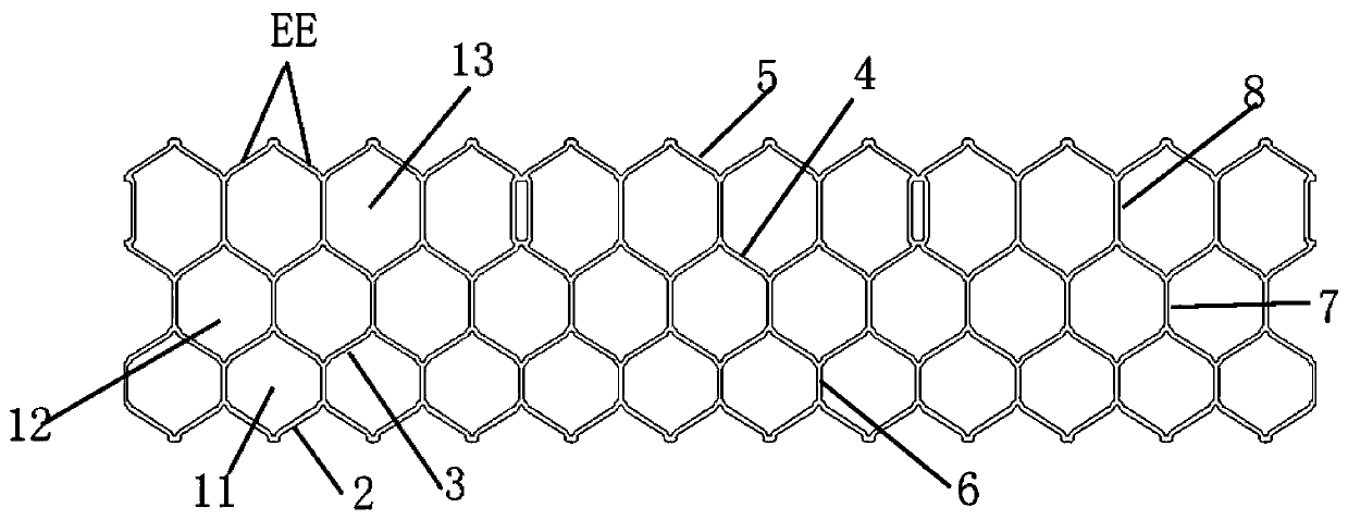
[0021] refer to figure 2 and image 3 As shown, a stent 1 for intervening valve-in-valve, the stent is a metal mesh tube, and the stent 1 has four rows of circumferential struts 2, 3, 4, 5 extending transversely, each row of circumferential struts A plurality of axial struts 6, 7, 8 are arranged between them, and the axial struts of each row are arranged alternat...


PUM


Abstract

The invention relates to a stent used for valve-in-valve intervention. The stent is a metal net pipe, and is provided with four rows of circumferential supporting rods which transversely extend and multiple columns of axial supporting rods which are arranged among the circumferential supporting rods, wherein the rows of axial supporting rods are arranged in a cross mode, the axial supporting rodsare connected with the transverse supporting rods to form honeycombed grids which are distributed in a cross mode, the area of the honeycombed grids at an inflow end and the area of the honeycombed grids of the middle row are basically the same, and the area of the honeycombed grids at an outflow end is a little lager than that of the honeycombed grids of the other two rows. According to the stentused for valve-in-valve intervention, considering that for valve-in-valve intervention, a valve-in-valve needs to intervene in a damaged surgical valve or interventional valve which is implemented before, due to the specificity of fitting of the valve-in-valve and the damaged failed valve, an existing intervention valve support is modified subversively, and all grids of the stent are of structures similar to honeycombs, so that the stent of the structure not only has certain rigidity, but also has high tenting speed and good adhesion, and a better use effect is obtained.

Description

technical field [0001] The invention relates to the technical field of medical devices, in particular to a connection structure for a stent and a leaflet of an interventional valve-in-valve or an interventional pulmonary valve, and an interventional valve-in-valve and an interventional pulmonary valve using the connection structure. Background technique [0002] With the continuous growth of my country's economic level and the increasing number of biological valve replacements for elderly patients with valvular disease, the application ratio of biological valves continues to approach developed countries. The guidelines issued by AHC / ACC in 2017 reduced the age of patients with surgically implanted biological valves to 50 years old, and recommended the use of biological valves for patients of any age who are contraindicated in anticoagulation therapy, cannot be properly anticoagulated or do not want anticoagulation therapy . In addition, in recent years, the application of t...

Claims


Application Information

Patent Timeline
Patent Type & Authority Applications(China)
IPC IPC(8): A61F2/24
CPCA61F2/2418A61F2/2463A61F2230/0017A61F2230/0069A61F2230/0054A61F2/90A61F2002/825
Inventor 金磊范志豪慕宏
Owner BEIJING BALANCE MEDICAL
Why Eureka
Try Eureka