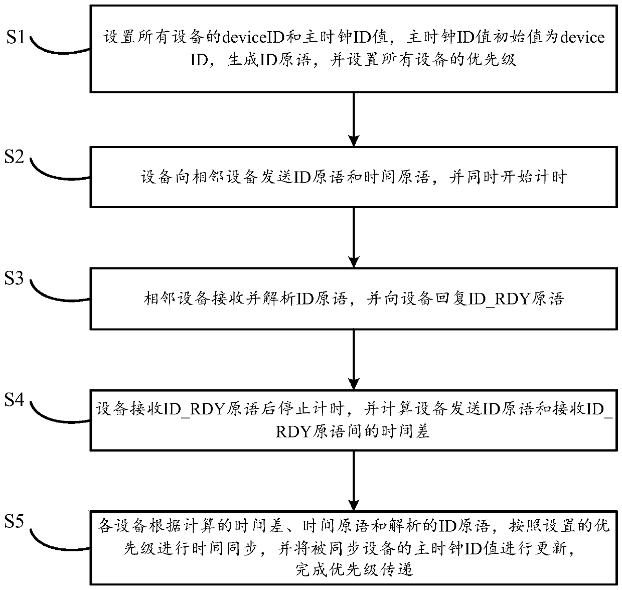
A method for time synchronization of fc network based on complex network structure
A technology of network structure and network time, which is applied in the direction of multiplexing communication, time division multiplexing system, electrical components, etc., can solve the problems that the priority of FC equipment cannot be transferred, and the time of FC network cannot be synchronized, etc., so as to avoid failure Synchronization, to achieve the effect of dynamic fault tolerance
- Summary
- Abstract
- Description
- Claims
- Application Information
AI Technical Summary
Problems solved by technology
Method used
Image
Examples
Embodiment 1
[0070] The FC network includes multiple switching devices, which are connected to each other, and each switching device is connected to multiple FC devices, such as Figure 5 shown;
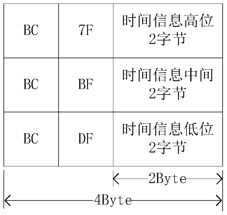
[0071] In this example, five switching devices constitute the Figure 7 The ring structure shown. The steps for time synchronization between device 1 and device 5 will be described in detail below, and the steps for time synchronization among other devices are the same. To facilitate the distinction between ID primitives and ID_RDY primitives in device 5 and device 1, specifically, ID primitives will be described as ID primitives 5 and ID primitives 1, and ID_RDY primitives will be described as ID_RDY primitives respectively. Language 5 and ID_RDY primitive 1; among them, ID primitive 5 represents the primitive containing the device ID of device 5, ID primitive 1 represents the primitive containing the device ID of device 1, and the device ID of device 1 is 0x01, and device 2 The device ID of ...
Embodiment 2
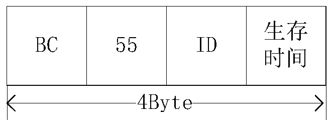
[0091] The time-to-live is set in the ID primitive of the device in this application, and the time-to-live can improve the fault tolerance of the method; the time-to-live set by each device is 0xff, and the time-to-live is subtracted by 1 each time the ID primitive is sent. If the adjacent device fails, the survival time in the register will not be updated, and the survival time will be decremented to 0x00. At this time, the device will re-initiate synchronization, and the main clock ID value in the register will be configured as the local device ID. Configured as 0xff.
[0092] exist Figure 8 In the linear structure, the device ID of device 1 is 0x01, the device ID of device 2 is 0x02, the ID of device 3 is 0x03, the ID of device 4 is 0x04, and the initial survival time is 0xff. After the synchronization is completed, the master clock ID values of the devices are all updated to the device IDs with the highest priority, that is, the master clock ID values of devices 1 to...
PUM
 Abstract
Description
Claims
Application Information
 - R&D
- Intellectual Property
- Life Sciences
- Materials
- Tech Scout
- Unparalleled Data Quality
- Higher Quality Content
- 60% Fewer Hallucinations
Browse by: Latest US Patents, China's latest patents, Technical Efficacy Thesaurus, Application Domain, Technology Topic, Popular Technical Reports.
© 2025 PatSnap. All rights reserved.Legal|Privacy policy|Modern Slavery Act Transparency Statement|Sitemap|About US| Contact US: help@patsnap.com


